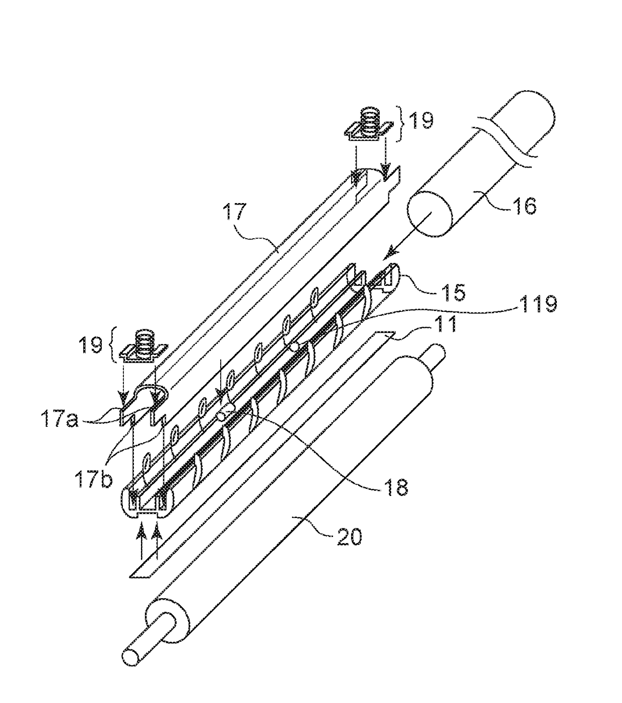
Fixing apparatus and heater used in same
- Summary
- Abstract
- Description
- Claims
- Application Information
AI Technical Summary
Benefits of technology
Problems solved by technology
Method used
Image
Examples
first exemplary embodiment
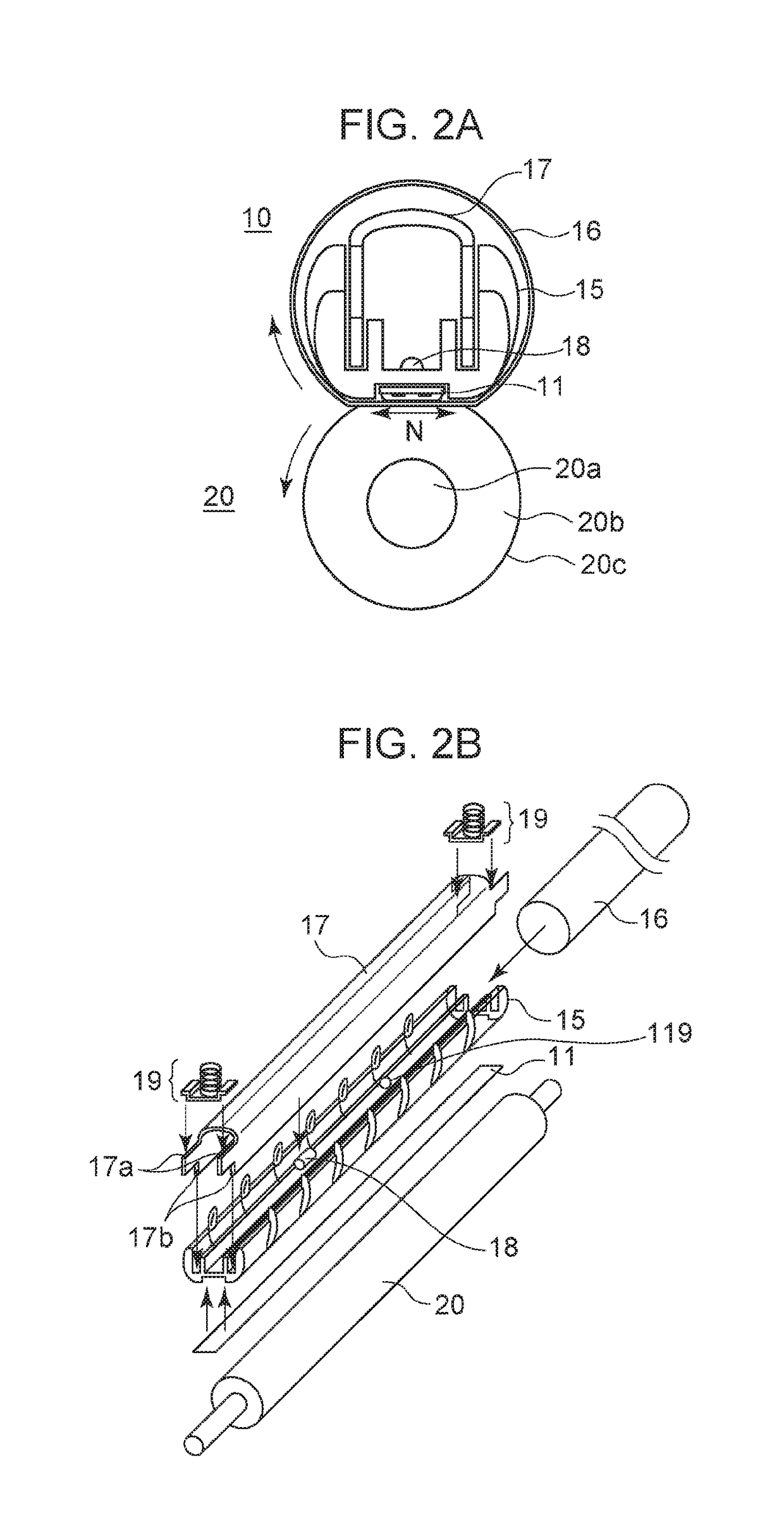
[0021]Hereinafter, configurations and advantages of an image forming apparatus, a fixing apparatus, and a heater according to the present exemplary embodiment will be described.
Image Forming Apparatus
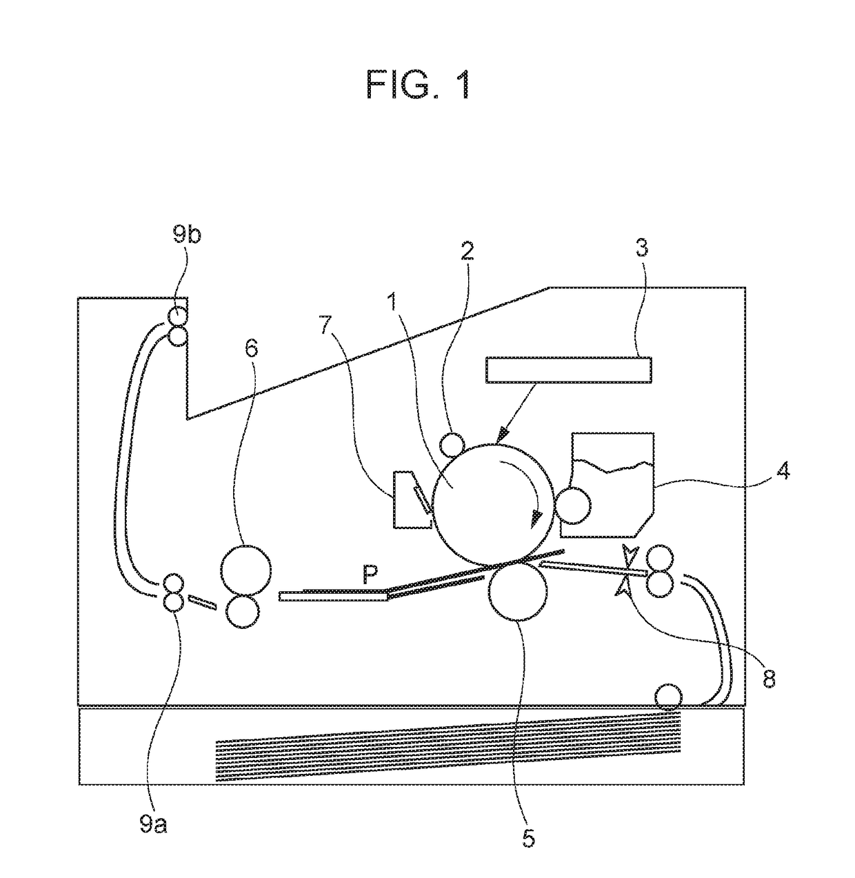
[0022]FIG. 1 is a schematic block diagram of an electrophotographic image forming apparatus according to the present exemplary embodiment.
[0023]A photosensitive drum 1 is a member in which a photosensitive portion is formed on a cylinder-shaped base formed of aluminum or nickel. The photosensitive drum 1 is first rotatably driven in the arrow direction, and a surface thereof is uniformly charged with a charging roller 2 serving as a charging apparatus. Subsequently, a laser scanner 3 performs scanning exposure on the photosensitive drum 1 with a laser beam controlled in accordance with image information, and an electrostatic latent image is formed. The electrostatic latent image is developed and made visible with a developing apparatus 4.
[0024]By applying a voltage to a transfer roller ...
second exemplary embodiment
[0056]The present exemplary embodiment is only different from the first exemplary embodiment in the pattern of the heat generating resistor 14 of the heater 11. Since the other configurations are similar to those of the first exemplary embodiment, description thereof is omitted.
Pattern of Heat Generating Resistor of Present Exemplary Embodiment
[0057]FIG. 6 is a diagram illustrating a shape of a heat generating resistor 24 of a heater 21 according to the present exemplary embodiment, and is a diagram that illustrates a pattern (shape) of the heat generating resistor 24 in the vicinity of an area (a width of 20 mm in the longitudinal direction) of the contact area B of the power shut-off member 18. In the present exemplary embodiment, similar to the first exemplary embodiment, at least a portion of an outline Lin24a of a first portion 24a-1 of a heat generating resistor 24a in area A is provided at a position closer to the power shut-off member 18 than the outline Lin24a of a second p...
first modification example
[0063]In the second exemplary embodiment, slopes with a predetermined angle are formed in the vicinity of the boundary portion of the heat generating resistor; however, in a first modification example of the second exemplary embodiment, the bend portions of the heat generating resistor 24 have a curved shape. Note that other than the configuration of the heat generating resistor at the boundary portion, the configuration of the first modification example is similar to that of the second exemplary embodiment.
[0064]FIG. 8 illustrates the heat generating resistor 24 according to the first modification example. While the angle θ formed in the second exemplary embodiment is 135°, in the present exemplary embodiment, the bend portions of the heat generating resistor 24 are arcs each having a radius of 4.5 mm.
[0065]The first portion and the third portion of the first modification example are also disposed close to the power shut-off member; accordingly, thermal stress acting on the heater ...
PUM
 Abstract
Description
Claims
Application Information
 - R&D
- Intellectual Property
- Life Sciences
- Materials
- Tech Scout
- Unparalleled Data Quality
- Higher Quality Content
- 60% Fewer Hallucinations
Browse by: Latest US Patents, China's latest patents, Technical Efficacy Thesaurus, Application Domain, Technology Topic, Popular Technical Reports.
© 2025 PatSnap. All rights reserved.Legal|Privacy policy|Modern Slavery Act Transparency Statement|Sitemap|About US| Contact US: help@patsnap.com


