Patient specific instruments and methods for joint prosthesis

a technology of joint prosthesis and patient, applied in the field of patient specific instruments and methods for joint prosthesis, can solve the problems of time-consuming dissection, ineffectiveness, and inability to expose and consistently locate, and achieve the effect of difficult to expos

Active Publication Date: 2018-10-11
HOWMEDICA OSTEONICS CORP
View PDF3 Cites 18 Cited by
  • Summary
  • Abstract
  • Description
  • Claims
  • Application Information

AI Technical Summary

Benefits of technology

[0018]In various methods, one or more reference bushing is inserted prior to CT scanning or other imaging technique and surgery. The method can happen in two phases. First the bushings can be placed, in some embodiments percutaneously. Later, e.g., an hour or several hours, a day or several days to several weeks later, the location information can be obtained. Subsequently, e.g., an hour or several hours, a day or several days t

Problems solved by technology

This variation introduces complexity in exposing and consistently locating a landmark to be used as a registration point.
Whil

Method used


Image

  • Patient specific instruments and methods for joint prosthesis
  • Patient specific instruments and methods for joint prosthesis
  • Patient specific instruments and methods for joint prosthesis

Examples


Embodiment Construction

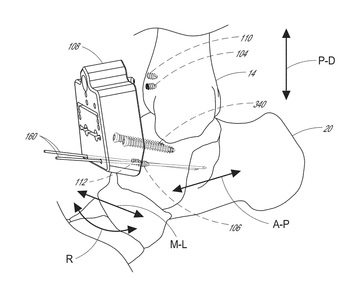
[0045]This application is directed to patient specific instruments, such as cutting guides, tools, and methods that can be used in joint procedures. The tools can be used to place an ankle prosthesis, a shoulder or other prosthesis and, in some cases, correct deformity in a joint. As discussed in greater detail below the apparatuses and methods herein enable the bones around a joint to be prepared with minimal incisions and relatively little to no soft tissue scraping. While small incisions may be formed for cutting bones and introducing prosthesis components, the apparatuses and methods herein allow a surgeon to avoid excessive incisions and excessive tissue removal around the bone. For instance these apparatuses and methods can enable a surgeon to not disturb or minimally disturb the periosteum, which is a dense connective tissue attached to the bone which in prior art methods is required to be mostly or completely scraped off the bone.

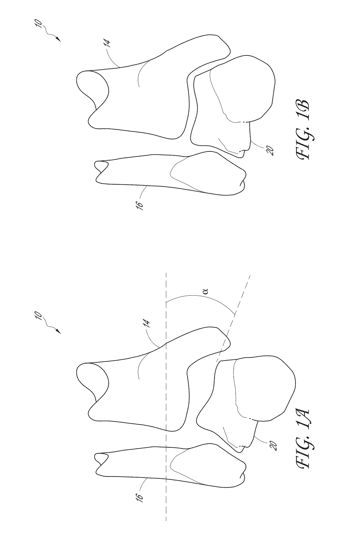
[0046]FIG. 1A shows an ankle joint 10 in a st...


PUM


Abstract

A system for preparing an ankle bone to receive an ankle prosthesis is provided. The system includes a patient specific cutting guide that has an anterior surface, a posterior surface, and at least one cutting feature extending through the guide from the anterior surface. The posterior surface comprising a first protrusion or other member that extends from a first end fixed to the posterior surface to a second end disposed away from the first end of the first protrusion. The posterior surface has a second protrusion or other member that extends from a first end fixed to the posterior surface to a second end disposed away from the first end of the second protrusion. The first and second protrusions are spaced apart and have a length such that when the patient specific cutting guide is coupled with first and second bone references, which can include bushings implantable in bones, a clearance gap is provided between the posterior surface and the ankle bone.

Description

INCORPORATION BY REFERENCE TO ANY PRIORITY APPLICATIONS[0001]Any and all applications for which a foreign or domestic priority claim is identified in the Application Data Sheet as filed with the present application are hereby incorporated by reference under 37 C.F.R. § 1.57.BACKGROUND OF THE INVENTIONField of the Invention[0002]This application is directed to methods and apparatuses used to install a joint prosthesis using patient specific instruments.Description of the Related Art[0003]Patient specific instruments (PSI) refer to specially manufactured instruments that incorporate the patient's own bone geometry data. The instruments can be accurately positioned because they are formed with reference to the patient's bone data and when formed in this manner have features that engage selected landmarks on the bone to assure proper positioning. An imaging technology, such as computerized tomography (CT) scanning, is used to acquire the bone data prior to surgery. Three dimensional (3D...

Claims


Application Information

Patent Timeline
IPC IPC(8): A61B17/17A61B17/15A61B34/10
CPCA61B17/1775A61B17/15A61B34/10A61B2017/90A61B2034/105A61B2017/568A61B2034/108A61B17/90
Inventor MAULDIN, RICHARD GARRETFLANAGAN, THOMAS ANTHONYLIZEE, EMMANUEL FRANCOIS MARIE
Owner HOWMEDICA OSTEONICS CORP
Why Eureka
Try Eureka