Plate selection user interface and design tool with database

a plate selection and database technology, applied in the field of orthopedic surgery, can solve the problems of shortening the duration and difficulty of the correction procedure, affecting the quality of life of patients, etc., and achieve the effect of increasing the relative density

Active Publication Date: 2018-10-11
STRYKER EURO OPERATIONS HLDG LLC
View PDF14 Cites 5 Cited by
  • Summary
  • Abstract
  • Description
  • Claims
  • Application Information

AI Technical Summary

Benefits of technology

[0013]A second aspect of the present invention is also a bone plate for correcting a deformity in first and second bone portions having a deformed position with respect to each other. In the second aspect, the bone plate may include a body having first and second sections and superior and inferior surfaces, the inferior surface having a preoperatively planned shape to match an outer surface of each of the first and second bone portions when the first and second bone portions are in a corrected position different than the deformed position, the body also having at least one fixation hole adapted to contact an area of the first or second bone portions having higher relative density.

Problems solved by technology

Use of a standard bone plate can shorten the duration and difficulty of the correction procedure.
However, a bone plate of standard size and shape may be undesirable for a few reasons.
As one example, a standard bone plate may not fit special situations or complex anatomy.
Also, a standard bone plate may cause pain and discomfort for a patient.
This may occur when a bone-contacting surface of a standard bone plate does not correspond well with a patient's bone anatomy.
Further, a standard bone plate may negatively impact the healing process.
In some cases, the location and number of screw holes on the standard bone plate is not sufficient for proper plate fixation.
For example, if the location of a screw hole corresponds to a weak bone area in a patient with osteoporosis, then the bone plate may not be properly secured and the one or more bone portions may not be properly aligned.
Often, a surgeon may need to perform bone cuts at multiple angles, which can be difficult for special situations or complex anatomy.

Method used


Image

  • Plate selection user interface and design tool with database
  • Plate selection user interface and design tool with database
  • Plate selection user interface and design tool with database

Examples


Embodiment Construction

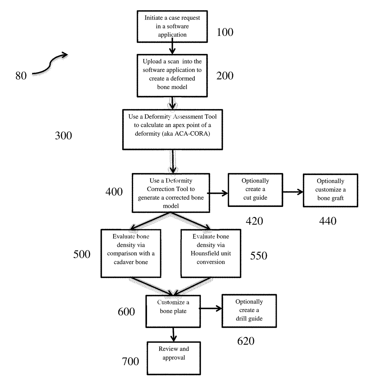
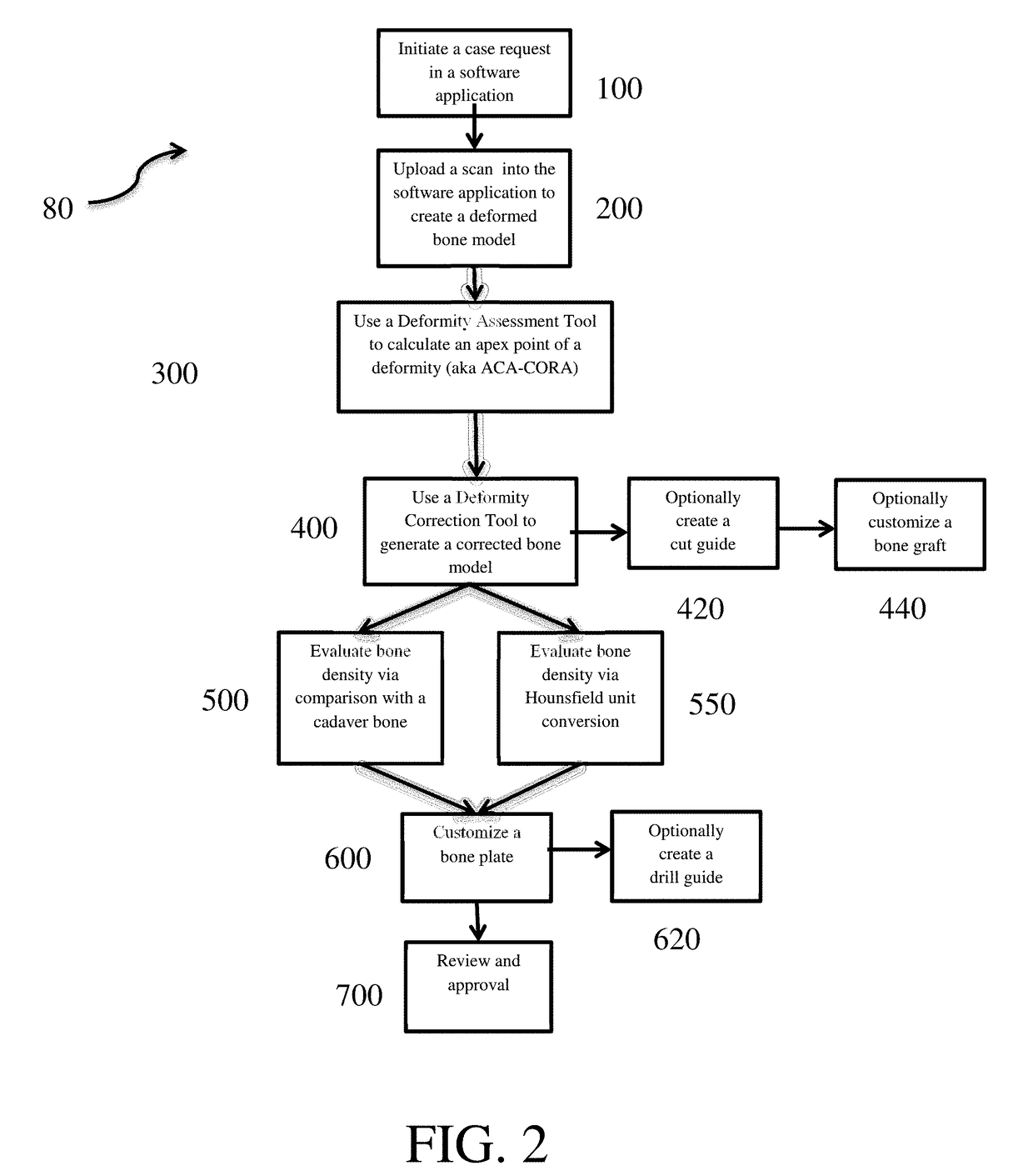
[0072]Those of skill in the art can recognize that the following description is merely illustrative of the principles of the invention, which may be applied in various ways to provide many different alternative embodiments.

[0073]Depending on the application, a surgeon may choose to use a customized bone plate or a prefabricated bone plate.

[0074]The following paragraphs will describe the creation and use of a fully-customized patient specific bone plate. A fully-customized bone plate may provide better deformity correction, for example, when treating special situations or complex anatomy. A fully-customized bone plate having a preoperatively planned shape to match the outer surface of the patient's bone anatomy may also reduce pain and discomfort and / or promote the healing process. It also can help the surgeon ensure proper plate alignment and fixation during the surgery.

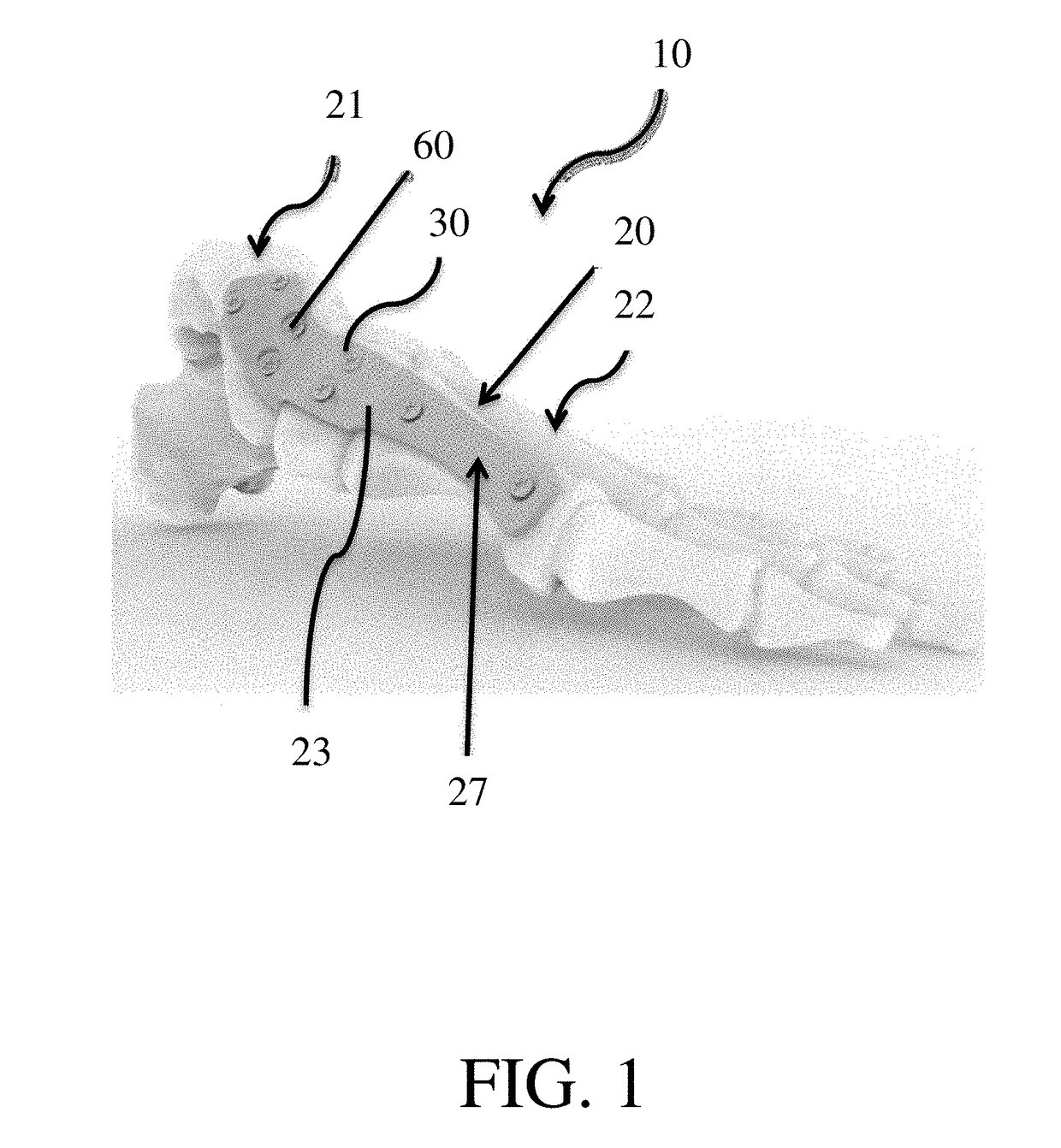
[0075]FIG. 1 shows a patient-specific plating system 10 according to one embodiment of the present invention. Syst...


PUM


Abstract

Described herein are systems and methods in which a surgeon can use computer-implemented deformity assessment and correction tools to create 3D models of a bone. To ensure adequate healing, a surgeon may choose to use a prefabricated bone plate, a semi-customized bone plate, or a fully-customized bone plate to hold first and second bone portions in a corrected position. To select the appropriate prefabricated bone plate, the surgeon may identify three landmark locations on the first and second bone portions corresponding to desired fixation hole locations on the bone plate. The surgeon can then use a software application to evaluate multiple bone plate designs in a library and compare the average proximity of the landmark locations to fixation hole locations on each of the bone plate designs. Then, the surgeon can determine which bone plate design best fits the patient anatomy based on his comparison.

Description

CROSS-REFERENCE TO RELATED APPLICATIONS[0001]This application claims the benefit of the filing date of U.S. Provisional Patent Application No. 62 / 482,422 filed Apr. 6, 2017, the disclosure of which is hereby incorporated herein by reference.TECHNICAL FIELD[0002]The present disclosure generally relates to orthopedic surgeries involving bone plating systems and methods of bone plate fixation. Particularly, disclosed herein is a patient-specific plating system that may include a best-fit bone plate, a semi-customized bone plate, or a fully-customized bone plate, in addition to methods of creating and using said bone plates.BACKGROUND OF THE INVENTION[0003]Bone plating systems are often used to correct bone deformities resulting from trauma or degenerative conditions. For example, surgeons use bone plating systems to set or stabilize bone portions in cases involving fractures, osteotomies, or other deformity conditions.[0004]In many applications, a bone plate is used to hold one or more...

Claims


Application Information

Patent Timeline
Patent Type & Authority Applications(United States)
IPC IPC(8): A61B34/10A61B17/80
CPCA61B34/10A61B17/8061A61B2034/108A61B17/1775A61B17/8095A61B17/151A61B17/152A61B17/80A61B2017/568
Inventor SINGH, MANOJ KUMARKUMAR, ANUP
Owner STRYKER EURO OPERATIONS HLDG LLC
Why Eureka
Try Eureka