Light guide optical assembly

a technology of optical assemblies and light guides, applied in the field of optical assembly, can solve the problems of significant drawbacks in configuration and limited fov, and achieve the effect of achieving limited fov

Active Publication Date: 2018-10-11
LUMUS LTD
View PDF1 Cites 59 Cited by
  • Summary
  • Abstract
  • Description
  • Claims
  • Application Information

AI Technical Summary

Problems solved by technology

Despite the compactness of this configuration, this configuration suffers significant drawbacks.
In particular, only a very limited FOV can be achieved.

Method used


Image

  • Light guide optical assembly
  • Light guide optical assembly
  • Light guide optical assembly

Examples


Embodiment Construction

—FIGS. 8A to 15D

[0073]The principles and operation of the apparatus according to a present embodiment may be better understood with reference to the drawings and the accompanying description. A present invention is an optical assembly for optical aperture expansion. The apparatus combines facet reflective technology (reflective components) with diffractive technology (diffractive components). Innovative embodiments with diffractive components use at least two components having opposite optical power (matching), so that chromatic dispersion introduced by a first diffractive component will then be cancelled by a second diffractive component. The two diffractive components are used in combination with a reflective optical component to achieve more efficient aperture expansion (for near eye display), reducing distortions and noise, while also reducing design constraints on the system and individual components, as compared to conventional techniques.

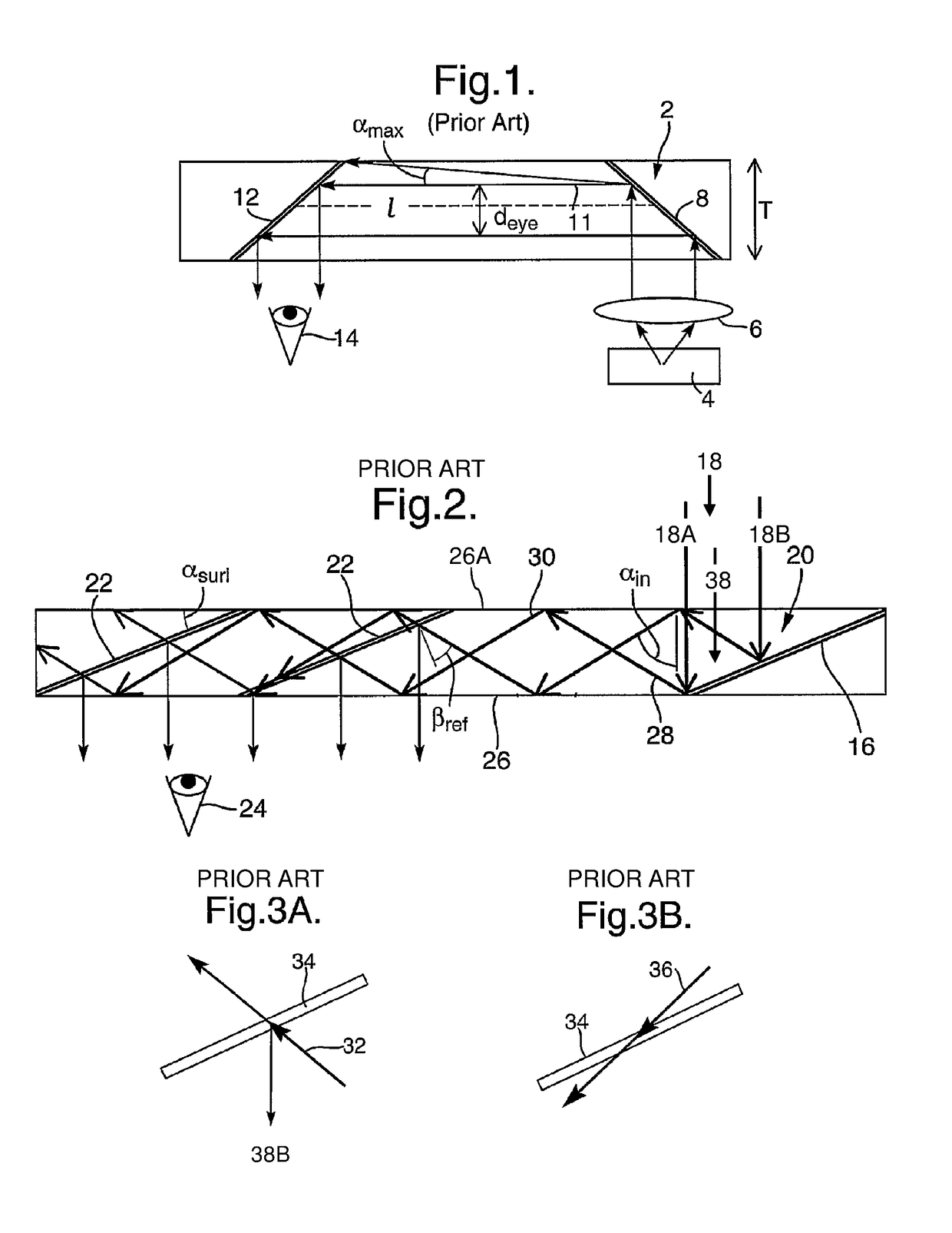
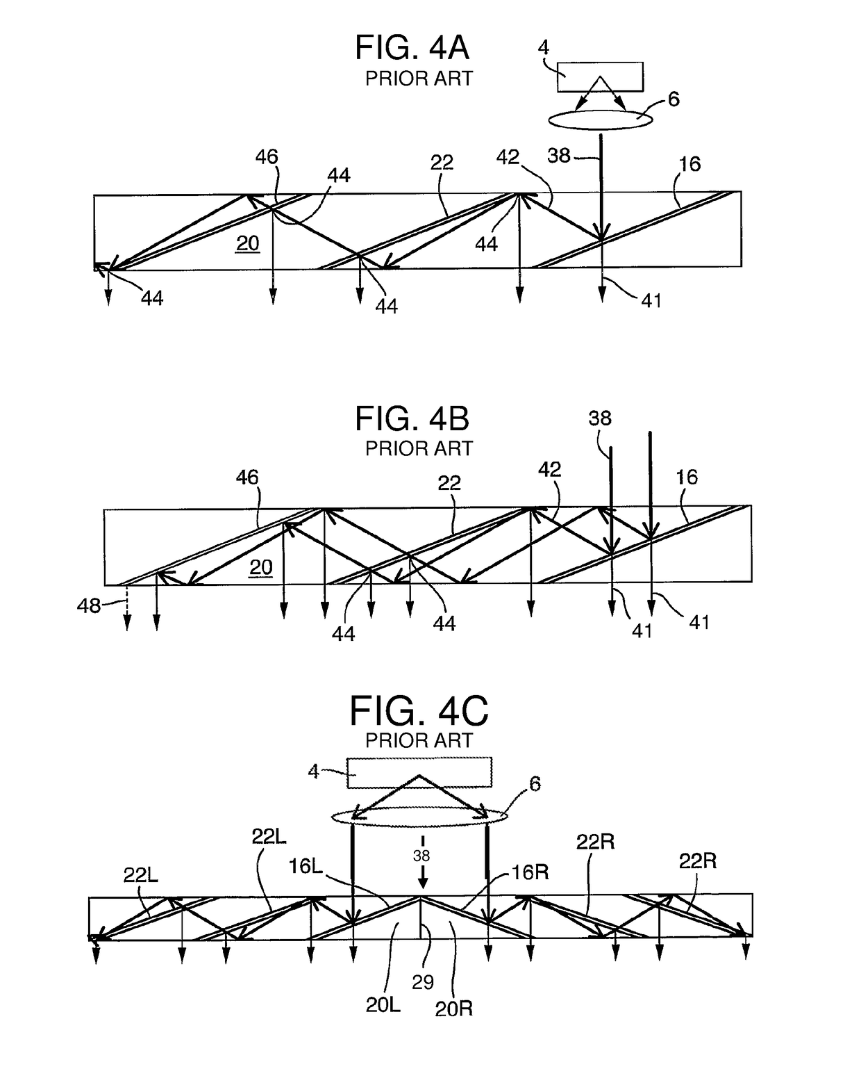
[0074]Current, conventional optical ap...


PUM


Abstract

An optical assembly for optical aperture expansion combines facet reflective technology with diffractive technology. At least two diffractive components having opposite optical power (matching) are used, so that chromatic dispersion introduced by the first diffractive component will then be cancelled by the second diffractive component. The two diffractive components are used in combination with a reflective optical component to achieve more efficient aperture expansion (for near eye display), reducing distortions and noise, while also reducing design constraints on the system and individual components, as compared to conventional techniques. The assembly eliminates and / or reduces the need for polarization management, while enabling wider field of view. In addition, embodiments can have reduced nonuniformity, as compared to conventional single technology implementations, since the distortion patterns of the two technologies do not correlate.

Description

FIELD OF THE INVENTION[0001]The present invention generally relates to optical assemblies, and in particular, it concerns optical aperture expansion.BACKGROUND OF THE INVENTION—FIG. 7A TO FIG. 7B[0002]Referring to FIG. 7A, there is shown a rough sketch of conventional optical aperture expansion using diffractive components in a waveguide. In the current figure, incoming light (image) is vertical from outside the page into the page. Coupling-in element 1001 couples the incoming light into lateral expansion element 1002, which expands the light laterally (from left to right in the current figure). Then the laterally expanded light is coupled into vertical expansion element 1003 which expands the light vertically (from top to bottom in the current figure), and couples-out the light to a user (eye of a viewer).[0003]Conventional diffractive elements introduce chromatic dispersion where light-rays with different wavelengths diffract at different angles. To reduce chromatic dispersion nar...

Claims


Application Information

Patent Timeline
Patent Type & Authority Applications(United States)
IPC IPC(8): F21V8/00G02B27/01
CPCG02B6/0016G02B27/0172G02B6/0075G02B6/0028G02B6/0038G02B2027/0125G02B2027/0116G02B6/0031G02B6/0055G02B27/0081G02B5/18G02B27/10G02B27/28G02B6/34G02B6/00
Inventor DANZIGER, YOCHAY
Owner LUMUS LTD
Why Eureka
Try Eureka