Battery pack

a battery pack and battery technology, applied in battery, secondary cell servicing/maintenance, cell components, etc., can solve the problems of detachment of the bus bar from the external terminal, damage to the welded portion, etc., to achieve the effect of ensuring the space for reworking, and reducing the risk of damag

Active Publication Date: 2018-10-11
TOYOTA JIDOSHA KK
View PDF2 Cites 4 Cited by
  • Summary
  • Abstract
  • Description
  • Claims
  • Application Information

AI Technical Summary

Benefits of technology

[0010]In a desired embodiment of the battery pack disclosed herein, the straight linear portion is formed at a position displaced, in the arrangement direction, from a center point of a portion where the terminal connection portion of the bus bar and the external terminal overlap with each other. This makes it easier to ensure the space for reworking the welded portion and preliminary welding.
[0011]In a desired embodiment of the battery pack disclosed herein, the relationship between the length L of the straight linear portion in the direction perpendicular to the arrangement direction and the radius R of the circular arc portion satisfies (R / L)<0.2. With such a relationship between the length L of the straight linear portion and the radius R of the circular arc portion, the breakage of the weld portion can be suppressed more effectively.
[0012]In a desired embodiment of the battery pack disclosed herein, a central angle θ of the circular arc portion is 30 degrees or more and 120 degrees or less. Within this range of the central angle θ of the circular arc portion, breakage of the welded portion can be suppressed more effectively.

Problems solved by technology

However, when a battery pack in which an external terminal of a unit cell and a bus bar are fixed by welding, as in WO 2014 / 050329, is mounted on a moving body such as a vehicle, the unit cells constituting the battery pack may move relative to each other due to vibrations during movement or impacts from the outside, stress may be repeatedly applied to the welded portion between the bus bar and the external terminal, and the welded portion may be damaged.
Breakage of the welded portion is undesirable since it can result in the detachment of the bus bar from the external terminal.

Method used


Image

  • Battery pack
  • Battery pack
  • Battery pack

Examples


Embodiment Construction

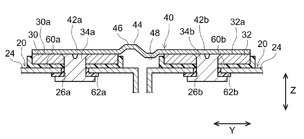
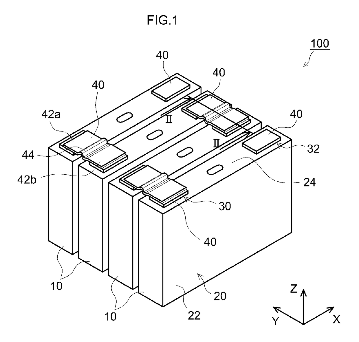
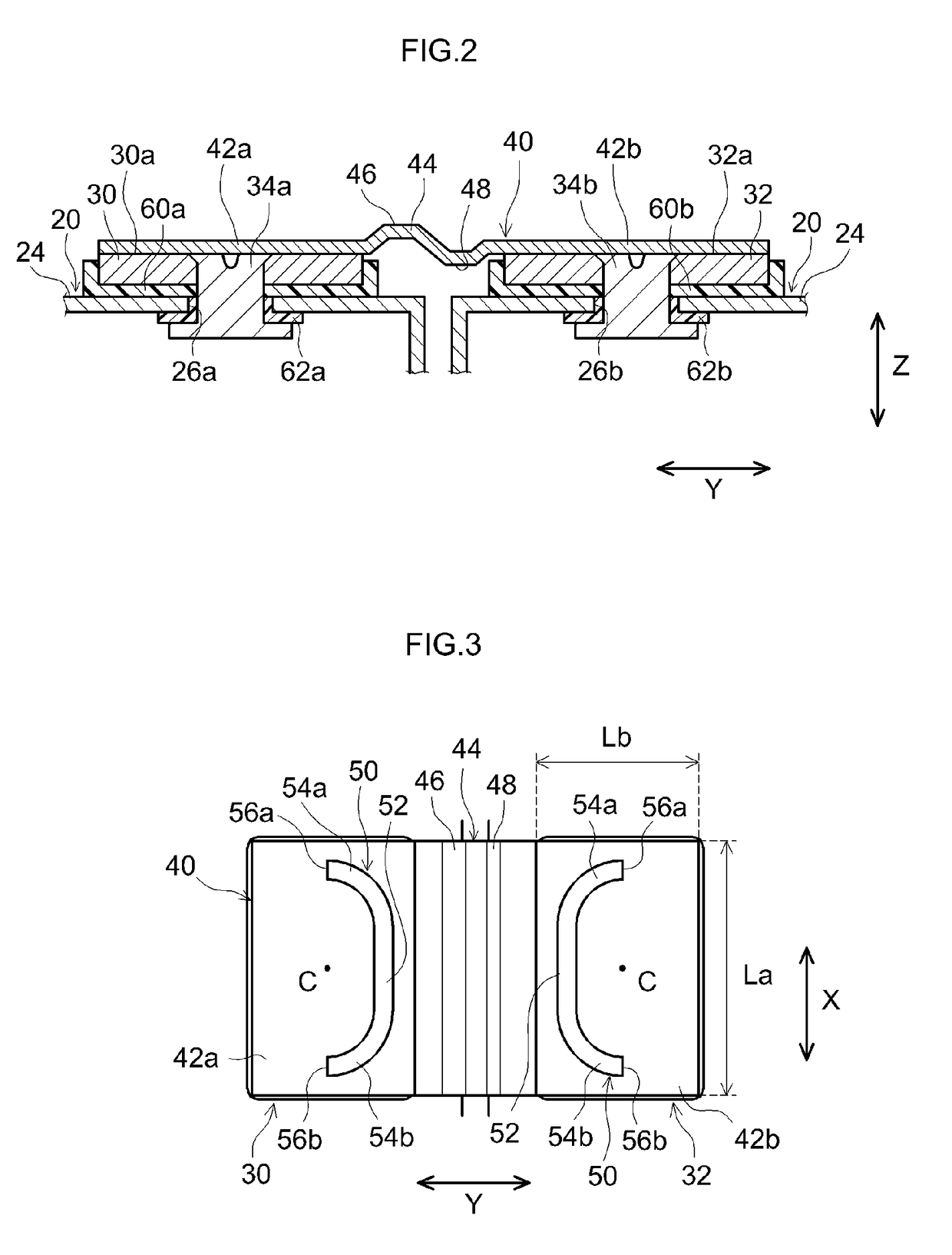
[0022]Embodiments of the present teaching will be described below with reference to the drawings. Matters which are other than those particularly mentioned in the present specification, but are necessary for the implementation of the present teaching (for example, the general configuration and manufacturing process of the electrode body not characterizing the present teaching) can be grasped as design matters for a person skilled in the art which are based on the related art in the pertinent field. The present teaching can be carried out based on the contents disclosed in this description and technical common sense in the pertinent field. Further, in the following drawings, the same reference numerals are assigned to members and parts that exhibit the same action. Further, the dimensional relationship (length, width, thickness, etc.) in each drawing does not reflect the actual dimensional relationship. In the description, A to B means A or more and B or less.

[0023]The battery pack a...


PUM

PropertyMeasurementUnit
central angleaaaaaaaaaa
thicknessaaaaaaaaaa

Abstract

The battery pack disclosed herein includes a plurality of unit cells. The plurality of unit cells is connected to each other by a bus bar. The bus bar has two terminal connection portions and a linking portion. A linear welded portion is formed in a portion where the terminal connection portions and the external terminals overlap with each other. The linear welded portion is non-annular in the plane of the terminal connection portions and has a straight linear portion extending in a direction orthogonal to the arrangement direction, and two circular arc portions that extend from respective ends of the straight linear portion and are curved toward a side opposite to the side where the linking portion is located.

Description

CROSS-REFERENCE[0001]This application claims priority based on Japanese Patent Application No. 2017-077840 filed on Apr. 10, 2017, the entire contents of which are incorporated herein by reference.BACKGROUND OF THE INVENTION1. Field of the Invention[0002]The present teaching relates to a battery pack. More specifically, the present teaching relates to a battery pack in which a plurality of unit cells is arranged, the unit cells being secondary batteries.2. Description of the Related Art[0003]A battery pack including a plurality of unit cells, each unit cell being a secondary battery such as a lithium ion secondary battery or a nickel hydride battery or a storage element such as a capacitor, is gaining importance as a power source to be mounted on a vehicle or a power source for a personal computer, a portable terminal, and the like. In particular, a battery pack using a lithium ion secondary battery, which is lightweight and capable of obtaining a high energy density, as a unit cell...

Claims


Application Information

Patent Timeline
Patent Type & Authority Applications(United States)
IPC IPC(8): H01M2/20H01M2/30H01M10/42H01M2/10H01M10/0525H01M2/26H01M50/209H01M50/50H01M50/505H01M50/51H01M50/522H01M50/55H01M50/562
CPCH01M2/206H01M2/30H01M10/4207H01M2/1077H01M10/0525H01M2/266H01M2220/20B60L50/64H01M50/50H01M50/51H01M50/505H01M50/55H01M50/209H01M50/522H01M50/562Y02E60/10Y02T10/70H01M50/502
Inventor NAGAI, HIROKITAMARU, KOJIKAGAMI, RYOOKAMOTO, YUKI
Owner TOYOTA JIDOSHA KK
Why Eureka
Try Eureka