Unlock instant, AI-driven research and patent intelligence for your innovation.

Converter apparatus having function of detecting failure of power device, and method for detecting failure of power device

a technology of converter apparatus and power device, which is applied in the direction of power supply testing, emergency protective arrangements for limiting excess voltage/current, instruments, etc., and can solve problems such as short circuit and damage to converter apparatus

Active Publication Date: 2018-10-11
FANUC CORP
View PDF5 Cites 7 Cited by
  • Summary
  • Abstract
  • Description
  • Claims
  • Application Information

AI Technical Summary

Benefits of technology

The patent describes a converter apparatus that can detect and prevent short circuits and damage caused by inputting a turn-on signal into power devices in a powered state. The apparatus includes a converter, a DC link capacitor, a voltage detector, a charging circuit, a charging circuit controller, a current detector, a turn-on controller, a switch, a power supply monitor, a threshold value setter, and a failure detector. The method involves connecting the power supply to the converter, charging the DC link capacitor, disconnecting the power supply, detecting the current flow, and determining if there is a failure of the power devices by comparing the detected current to a threshold value. The technical effect of this invention is to prevent damage to the converter apparatus and improve its reliability.

Problems solved by technology

However, in the case of a converter apparatus, inputting a turn-on signal into power devices in a powered state may cause a short circuit, and may damage the converter apparatus.

Method used


Image

  • Converter apparatus having function of detecting failure of power device, and method for detecting failure of power device
  • Converter apparatus having function of detecting failure of power device, and method for detecting failure of power device
  • Converter apparatus having function of detecting failure of power device, and method for detecting failure of power device

Examples


Embodiment Construction

[0013]A converter apparatus having the function of detecting a failure of a power device and a method for detecting the failure in the power device according to the present invention will be described below with reference to the drawings. However, the technical scope of the present invention is not limited to its embodiment, but encompasses the invention described in claims and equivalents thereof.

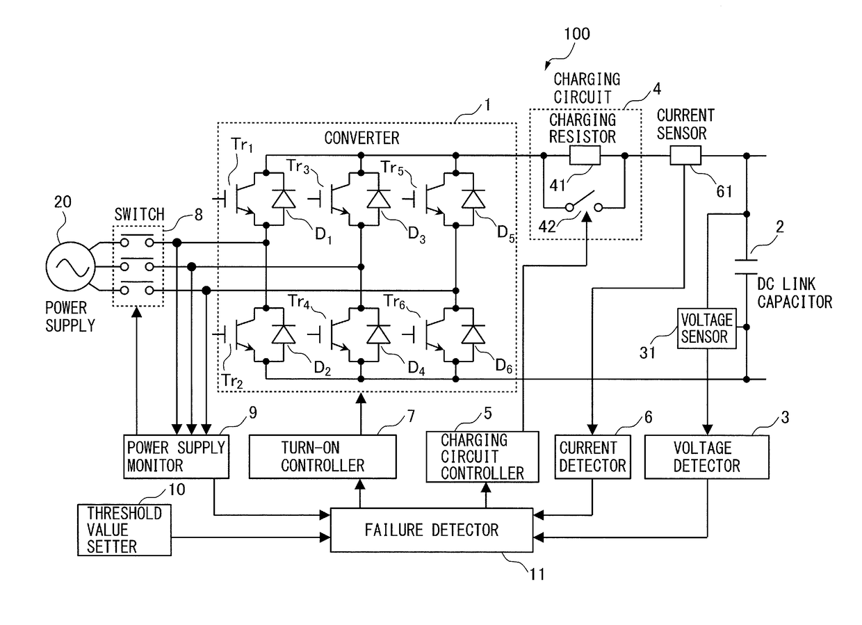
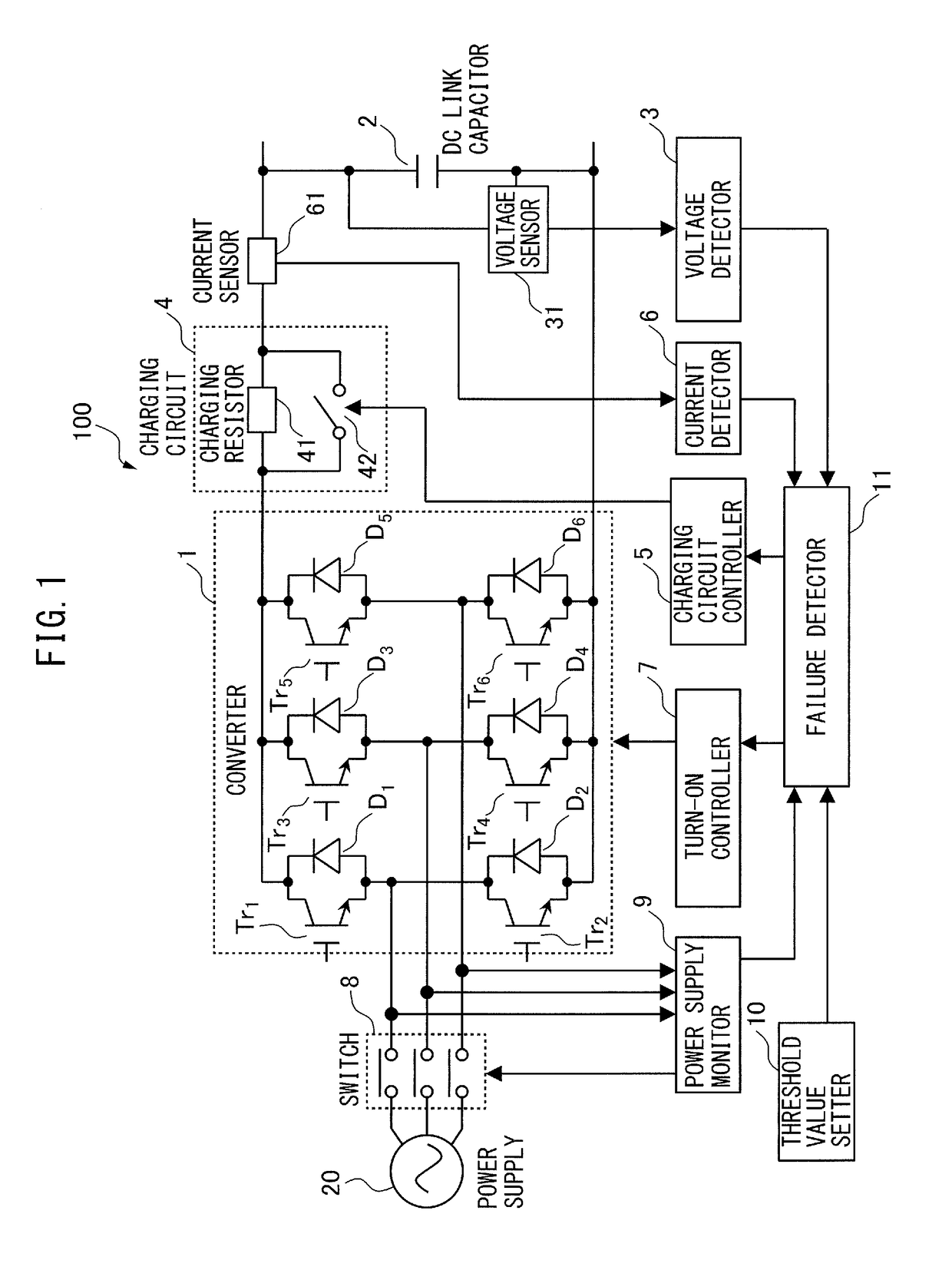
[0014]A converter apparatus having the function of detecting a failure of a power device according to an embodiment of this disclosure will be described. FIG. 1 is a block diagram of a converter apparatus according to the embodiment. A converter apparatus 100 includes a DC link capacitor 2, a voltage detector 3, a charging circuit 4, a charging circuit controller 5, a current detector 6, a turn-on controller 7, a switch 8, a power supply monitor 9, a threshold value setter 10, and a failure detector 11.

[0015]The converter 1 includes a plurality of (for example, six) power devices (Tr1 to T...


PUM


Abstract

A converter apparatus includes: a converter for converting an AC voltage into a DC voltage; a DC link capacitor connected to the converter; a voltage detector for DC link voltage; a charging circuit for the DC link capacitor; a charging circuit controller for a switch connected with a charging resistor; a current detector for detecting a current of the converter; a turn-on controller for controlling the turning-on of power devices; a switch for connecting or disconnecting a power supply; a power supply monitor for monitoring a connection state of the power supply; a threshold value setter for setting a first or second threshold value; and a failure detector for determining the presence or absence of the failure of the power devices by a comparison between a current flowing upon turning on the power device, immediately after disconnection of the power supply, and the first or second threshold value.

Description

[0001]This application is a new U.S. patent application that claims benefit of JP 2017-076983 filed on Apr. 7, 2017, the content of 2017-076983 is incorporated herein by reference.BACKGROUND OF THE INVENTION1. Field of the Invention[0002]The present invention relates to a converter apparatus having a function of detecting a failure of a power device, and a method for detecting the failure of the power device.2. Description of Related Art[0003]As a method for driving a motor by a motor drive device, a method in which an AC voltage inputted from a main power supply is converted into a DC voltage by a converter having a power transistor (power device), and the DC voltage is converted into an AC voltage to drive the motor by an inverter is generally known. When there is an abnormality in the power transistor, supplying AC power from the main power supply to the power transistor may damage the motor drive device. Thus, before supplying the AC power from the main power supply to the conve...

Claims


Application Information

Patent Timeline
IPC IPC(8): H02M1/32H02M7/219H02J7/00H02M1/08G01R31/50
CPCH02M1/32H02M7/219H02J7/0052H02M1/08H02J7/345H02M2001/0009H02M2001/0025H02M7/12G01R31/50H02M1/0009H02P29/027G01R31/40H02H7/1203H02H7/1225H02H9/001G01R31/52H02J7/00H02M1/0025H02H9/00G01R31/00H02P7/00
Inventor YOSHIDA, TOMOKAZU
Owner FANUC CORP
Features
  • R&D
  • Intellectual Property
  • Life Sciences
  • Materials
  • Tech Scout
  • Unparalleled Data Quality
  • Higher Quality Content
  • 60% Fewer Hallucinations
Learn More