Compressor

a compressor and compressor technology, applied in the field of compressors, can solve the problems of increasing the amount of refrigerant to be compressed together with the amount of refrigerant to be discharged, and achieve the effects of reducing oil loss, increasing the flow rate of refrigerant inside the compressor, and high operation capacity

Inactive Publication Date: 2018-10-18
DAIKIN IND LTD
View PDF0 Cites 0 Cited by
  • Summary
  • Abstract
  • Description
  • Claims
  • Application Information

AI Technical Summary

Benefits of technology

The present invention relates to a scroll compressor with a simplified structure that can improve performance and reduce oil loss. The compressor has a suction position that can be adjusted to control the oil volume and improve performance. The compressor can adjust the oil volume by controlling the position of the plunger and the oil passage, which can lead to a higher or lower oil level in the compression chamber. This allows for optimal oil control and prevents excessive oil from being supplied to the compression chamber, reducing oil loss and improving performance. The oil can be supplied to the compression chamber during adjustment of the suction volume using the oil passage, and the compressor can have a simple structure to improve performance and reduce oil loss.

Problems solved by technology

This increases the amount of refrigerating machine oil to be sucked together with the refrigerant to be supplied to a compression mechanism of the compressor, resulting in an increase in the amount of the refrigerating machine oil to be discharged together with the refrigerant compressed.

Method used


Image

  • Compressor
  • Compressor
  • Compressor

Examples


first embodiment

Variation of First Embodiment

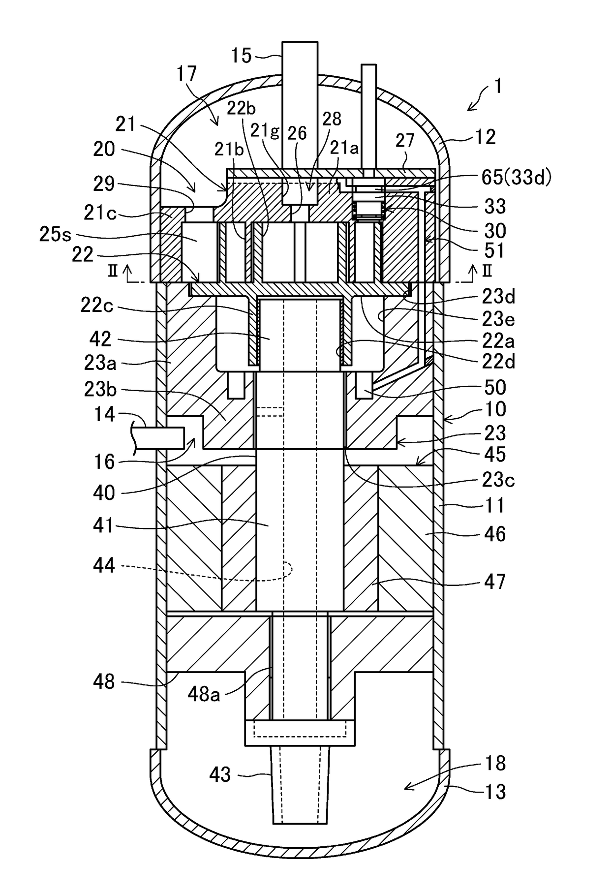
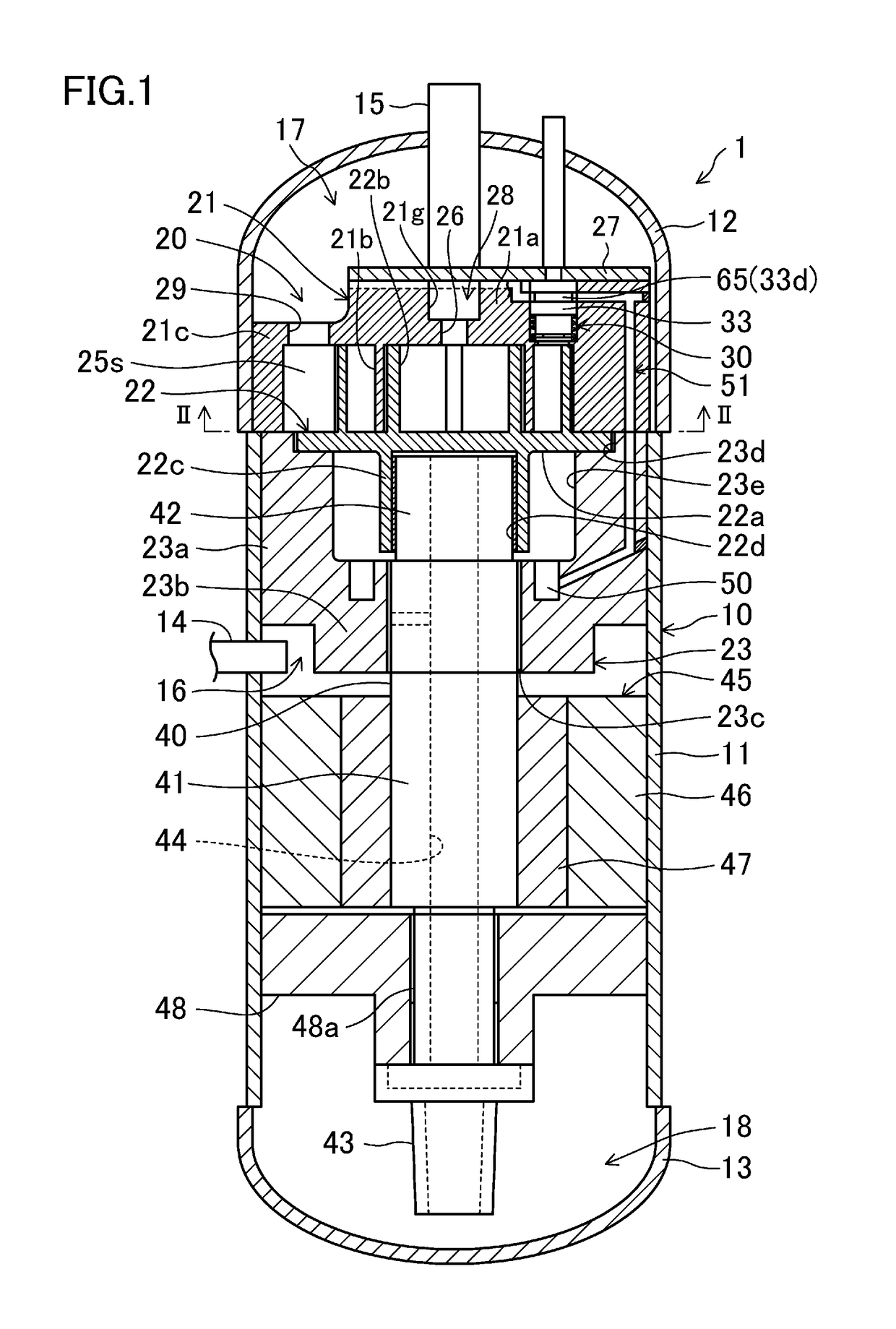
[0114]As shown in FIGS. 13 and 14, the oil passage (51) may include a passage (fixed scroll inner passage (53)) entirely passing through the inside of the fixed scroll (21) to communicate with the plunger (33) and the suction space (25s) of the compression mechanism (20). In this variation, the suction pipe (14) is connected to the suction port (29), and the transverse passage (53) of the oil passage (51) communicates with the suction port (29). Such a configuration allows the oil in the oil reservoir (50) to mix with the suction refrigerant and to be supplied to the compression chamber (25).

[0115]According to this variation, if only the adjustment operation at the low operation capacity is performed, oil is not sufficiently supplied to the compression chambers (25a, 25b), and the oil film having a thickness necessary for the compression mechanism is less likely to be formed, resulting in performance degradation. However, in this variation, if the oil pa...

second embodiment

[0116]Next, a second embodiment will be described.

[0117]In the second embodiment, as shown in FIGS. 15 and 16, the oil passage (51) includes an oil passage (55) closer to the orbiting scroll (hereinafter referred to as “the orbiting-scroll-side oil passage (55)”), and an oil passage (52) closer to the fixed scroll (hereinafter referred to as “the fixed-scroll-side oil passage (52)”) communicating with the orbiting-scroll-side oil passage (55). The orbiting-scroll-side oil passage (55) has one end communicating with the fixed-scroll-side oil passage (51), and the other end opposite to one end and communicating with the oil reservoir (18). Specifically, the end of the orbiting-scroll-side oil passage (55), which is opposite to one end communicating with the fixed-scroll-side oil passage (52), communicates with the oil reservoir (18) in the lower portion of the casing (10) through the oil supply passage (44) formed inside the drive shaft (41). An end of the fixed-scroll-side oil passag...

third embodiment

[0119]Next, a third embodiment will be described.

[0120]In the third embodiment, as shown in FIG. 17, the oil passage (51) has one end communicating with the oil reservoir (18) formed inside the casing (10), and the other end communicating with the suction space (25s) of the compression mechanism (20). Specifically, the oil passage (51) has an oil supply pipe (56) extending upward from the oil reservoir (18) inside the casing (10) and communicating with the plunger (33). This oil supply pipe (56) communicates with the transverse passage (53). In the oil passage (51), a space (the transverse passage (53)) between the plunger (33) and a suction side of the compression chamber (25) is the same as, or similar to, that of the variation of the first embodiment and the second embodiment.

[0121]The other configuration of this embodiment is the same as, or similar to, that of the second embodiment.

[0122]According to this third embodiment, if only the adjustment operation at the low operation c...


PUM


Abstract

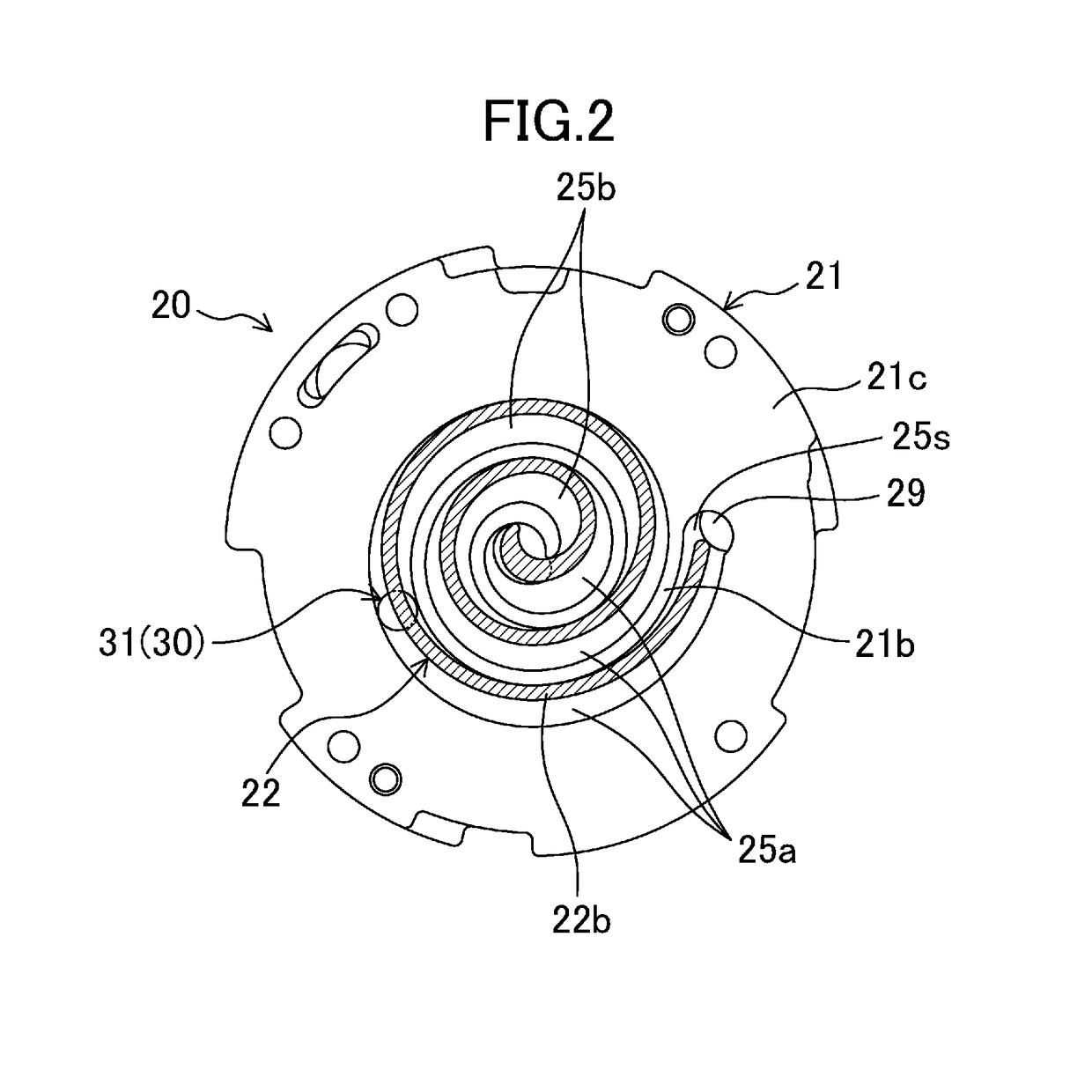
A compressor includes a compression mechanism housed in a casing. The compression mechanism includes a suction volume adjustment mechanism capable of switching a suction completion position of a compression chamber in a suction process between a first position and a second position with a smaller suction volume than the first position. The suction volume adjustment mechanism includes a plunger switchable between a closed position in which the suction completion position is moved to the first position and an open position in which the suction completion position is moved to the second position. An oil passage is arranged to allow an oil reservoir formed inside the casing and a suction space of the compression chamber to communicate with each other. The plunger is disposed midway along the oil passage, and includes a switching portion closing the oil passage in the closed position, and opening the oil passage in the open position.

Description

TECHNICAL FIELD[0001]The present disclosure is directed to a compressor including a suction bypass mechanism configured to change a position at which a suction process is completed and a compression process is started (hereinafter referred to as “suction completion position”) to adjust a suction volume. The present disclosure relates to a technique of solving lubricant shortage in a compression mechanism.BACKGROUND ART[0002]In conventional compressors, inverters are widely used to allow the compressors to be used in various operations ranging from an operation at a high rotational speed to an operation at a low rotational speed. Generally, during an operation at a high rotational speed, the flow rate of a refrigerant inside a compressor is increased. This increases the amount of refrigerating machine oil to be sucked together with the refrigerant to be supplied to a compression mechanism of the compressor, resulting in an increase in the amount of the refrigerating machine oil to be...

Claims


Application Information

Patent Timeline
Patent Type & Authority Applications(United States)
IPC IPC(8): F04C18/02F04C29/02
CPCF04C18/0215F04C29/02F04C23/008F04C28/16F04C18/0253F04C18/02
Inventor YAMADA, MASAHIRO
Owner DAIKIN IND LTD
Why Eureka
Try Eureka