
System and method for determining a distance to an object

a distance and object technology, applied in the field of systems for determining distances to objects, can solve the problems of limiting the prospect of miniaturization, reliability, and cost reduction of this type of system, and the attainable range of detection is very limited, so as to reduce the noise of readout, improve the signal-to-noise ratio, and reduce the effect of ambient light in the distance calculation formula

Active Publication Date: 2018-10-18
XENOMATIX NV
View PDF3 Cites 70 Cited by
  • Summary
  • Abstract
  • Description
  • Claims
  • Application Information

AI Technical Summary

Benefits of technology

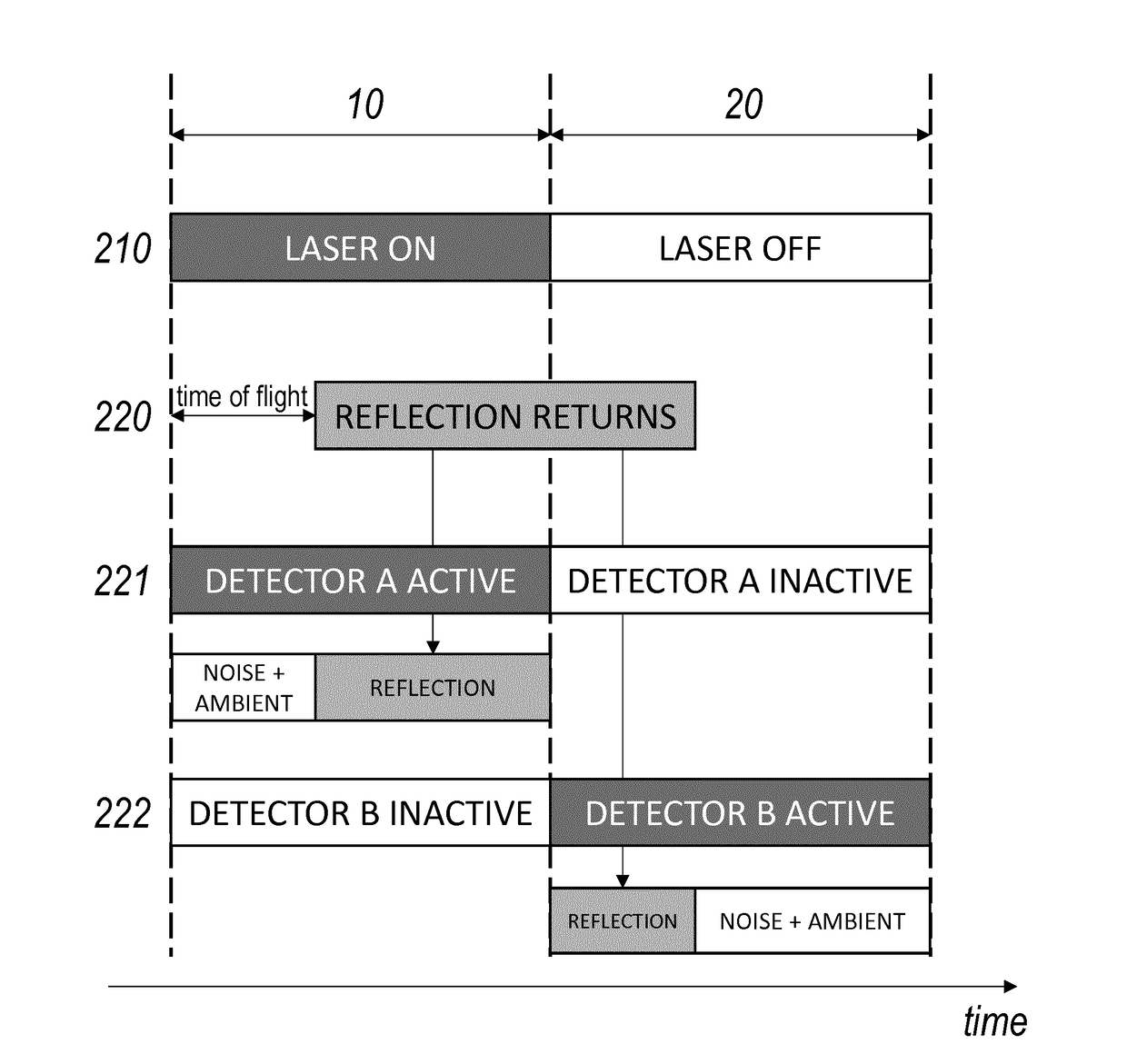
The present invention allows for the integration of a solid-state light source and a solid-state sensor on the same semiconductor substrate. The light source may be a VCSEL array or a laser with a grating. The invention also takes into account the impact of varying reflectivity of the object under study and the contribution of ambient light in the distance calculation algorithm. By accumulating charge in consecutive time windows, read-out noise is minimized, resulting in a better signal-to-noise ratio. The transmission and detection of the sequence of pulses may be repeated periodically. In an embodiment of the system, two equal time windows occur back-to-back, which allows for easy cancellation of the ambient light contribution in the distance calculation formula.

Problems solved by technology

In practice, these constraints turn out to make the RF modulated systems highly impractical for use in vehicular systems: the attainable range of detection is very limited for signal intensities that are within conventional safety limits and within the power budget of regular vehicles.
In addition, the use of mechanically rotating elements for scanning purposes limits the prospects for miniaturization, reliability, and cost reduction of this type of system.
At these pulse energy levels, and using ns pulses as presently used in DToF applications, the mere number of photons that can be expected to be usefully reflected by an object at a distance of 120 m is so low that it defeats detection by means of conventional semiconductor sensors such as CMOS or CCD or SPAD array.
Thus, increasing the VCSEL power outputs by 5 or 6 orders of magnitude, as would be required to extend the range of the known DToF systems, is physically impossible.
Even the use of avalanche diodes (AD or SPAD), which are theoretically sufficiently sensitive to capture the few returning photons, cannot be usefully deployed in the known LIDAR system architectures.
The serial read-out constraints of the solid state implementation limits the bandwidth of the system turning it inappropriate for the desired accuracy.
This is believed to be technically unfeasible in the context of current SPAD IC technology.
The above examples clearly indicate that the optical power emitted by present semiconductor lasers cannot meet the power requirements necessary for operations in the known LIDAR systems to be of practical use in automotive applications (e.g. for ranges up to 120 m).
However, the accuracy that can be achieved correlates with the triangulation base, which limits the further miniaturization that can be achieved.

Method used


Image

  • System and method for determining a distance to an object
  • System and method for determining a distance to an object
  • System and method for determining a distance to an object

Examples


Embodiment Construction

[0048]The surround sensing systems of the type disclosed in international patent application publication WO 2015 / 004213 A1, in the name of the present applicant, has the advantage of observing an extensive scene while illuminating that scene simultaneously or partially simultaneously only in a number of discrete and well-defined spots, in particular a predefined spot pattern. By using VCSEL lasers with an outstanding bundle quality and a very narrow output spectrum, it is possible to obtain a detection range with a limited amount of output power, even in the presence of daylight. The actual ranging performed in the system of WO 2015 / 004213 A1 relies on displacement detection, in particular triangulation, which was understood to be the only method practically available in the context of the long (quasi-stationary) pulse durations that were necessary in view of the power budget. To date, it had not been possible to achieve the same power / performance characteristics with a compact, sem...


PUM


Abstract

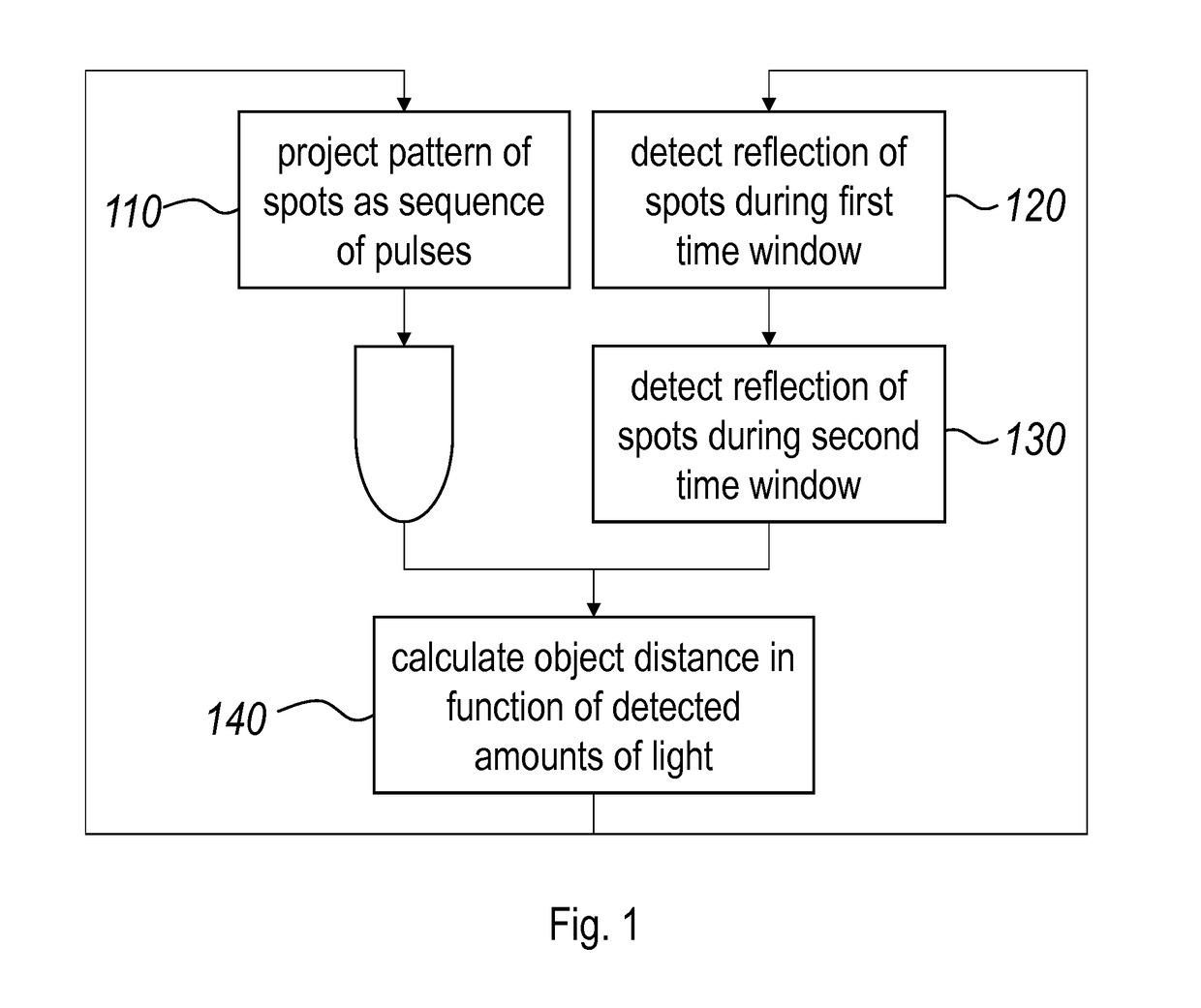
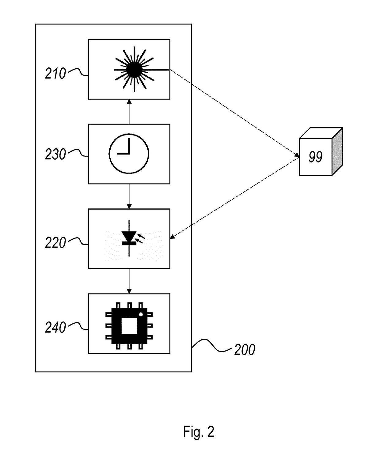
A system for determining a distance to an object including a solid-state light source for projecting a pattern of discrete spots of laser light towards the object in a sequence of pulses; a detector having a plurality of picture elements, for detecting light representing the pattern of discrete spots as reflected by the object in synchronization with the pulses; and a processor to calculate the distance to the object as a function of exposure values generated by the picture elements. The picture elements are configured to generate exposure values by accumulating, for each pulse of the sequence, a first amount of electrical charge representative of a first amount of light reflected by the object during a first time window and a second electrical charge representative of a second amount of light reflected by the object during a second time window, the second time window occurring after the first time window.

Description

FIELD OF THE INVENTION[0001]The present invention pertains to the field of systems for determining a distance to an object, in particular to time-of-flight based sensing systems to be used for the characterization of a scene or a part thereof.BACKGROUND[0002]In the field of remote sensing technology, mainly in the usage of making high-resolution maps of the surroundings, to be used in many control and navigation applications such as but not limited to the automotive and industrial environment, gaming applications, and mapping applications, it is known to use time-of-flight based sensing to determine the distance of objects from a sensor. Time-of-flight based techniques include the use of RF modulated sources, range gated imagers, and direct time-of-flight (DToF) imagers. For the use of RF modulated sources and range gated imagers, it is necessary to illuminate the entire scene of interest with a modulated or pulsed source. Direct time-of-flight systems, such as most LIDARs, mechanic...

Claims


Application Information

Patent Timeline
Patent Type & Authority Applications(United States)
IPC IPC(8): G01S17/10G01S7/481G01S17/02G01S17/93G01S17/89G01S17/894G01S17/18G01S17/86G01S17/931
CPCG01S17/107G01S7/4816G01S17/023G01S17/936G01S17/89G01S7/4814G01S17/10G01S17/42G01S17/931G01S17/894G01C3/06G01S17/18G01S17/86
Inventor VAN DYCK, DIRKVAN DEN BOSSCHE, JOHAN
Owner XENOMATIX NV
Learn More