
Implanted Medical Driveline Strain Relief Device

a technology of driveline and strain relief, which is applied in the field of implanted medical driveline strain relief devices, can solve the problems of mechanical fragility of the adhesion interface between the driveline and the skin, major medical interventions or deaths, tissue injury, etc., and achieves the effects of reducing adhesion stress, promoting tissue adhesion, and minimizing for

Inactive Publication Date: 2018-10-25
MEACHAM G B KIRBY
View PDF6 Cites 6 Cited by
  • Summary
  • Abstract
  • Description
  • Claims
  • Application Information

AI Technical Summary

Benefits of technology

The invention is a device that connects the driver to the patient's body, reducing stress on the skin and driver during normal and emergency activities. It is made of flexible elastomer bellows and seals that isolate the driver from body fluids and external contaminants, promoting tissue adhesion. The device is easily replaced if necessary and can be retrofitted to existing implants without removing the driver.

Problems solved by technology

The problem is that the adherent interface between the driveline and the skin is mechanically fragile.
Routine patient activities as well as accidental events result in torsional, pull and bending loads on the driveline that apply stresses to the adherent interface that often cause tissue injury and open a path for bacterial invasion and infection along the driveline path through the patient's tissue.
Such infections are a leading cause of complications, and may lead to major medical interventions or death.
In some cases the driveline cable is covered in velour to improve mechanical bonding through tissue ingrowth, but the stresses are often significant enough that injury and infection still occur.

Method used


Image

  • Implanted Medical Driveline Strain Relief Device
  • Implanted Medical Driveline Strain Relief Device
  • Implanted Medical Driveline Strain Relief Device

Examples


Embodiment Construction

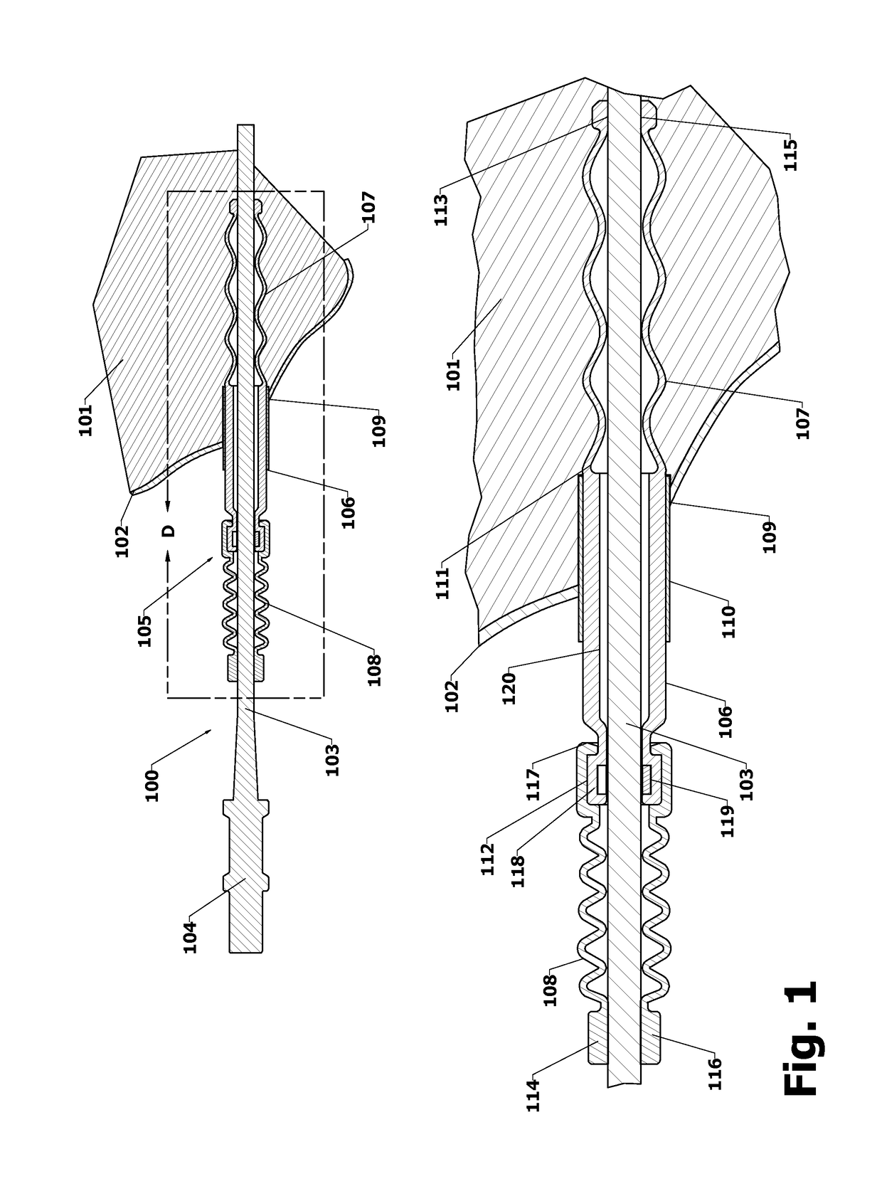
[0008]The following description and claims are in reference to implanted VAD system drivelines, but it is understood that the inventive device and methods are applicable to stress, injury and infection reduction for other implanted cables or tubes that exit through the skin. While the figures are schematic in that they show a linear geometry of the driveline and the device, in reality the driveline is flexible and will generally be curved. The device sleeve and bellows are formed from low modulus elastomers, and will therefore bend easily to follow the curvature of the driveline cable.

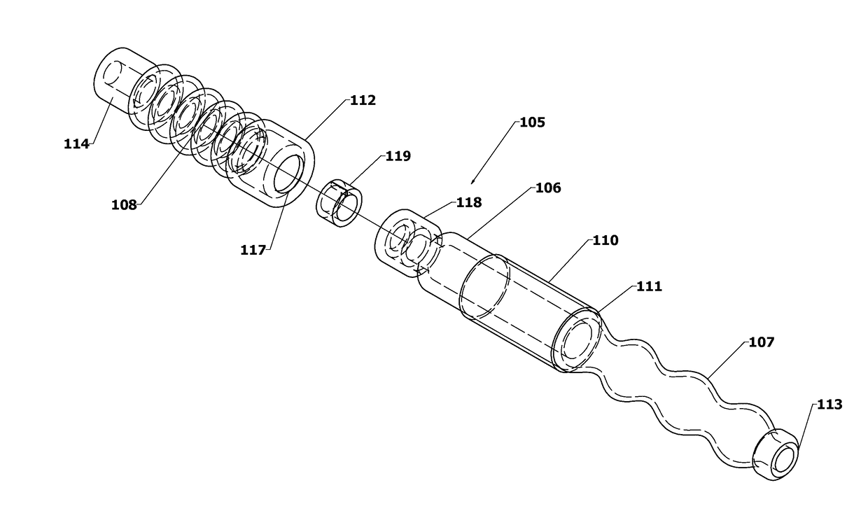
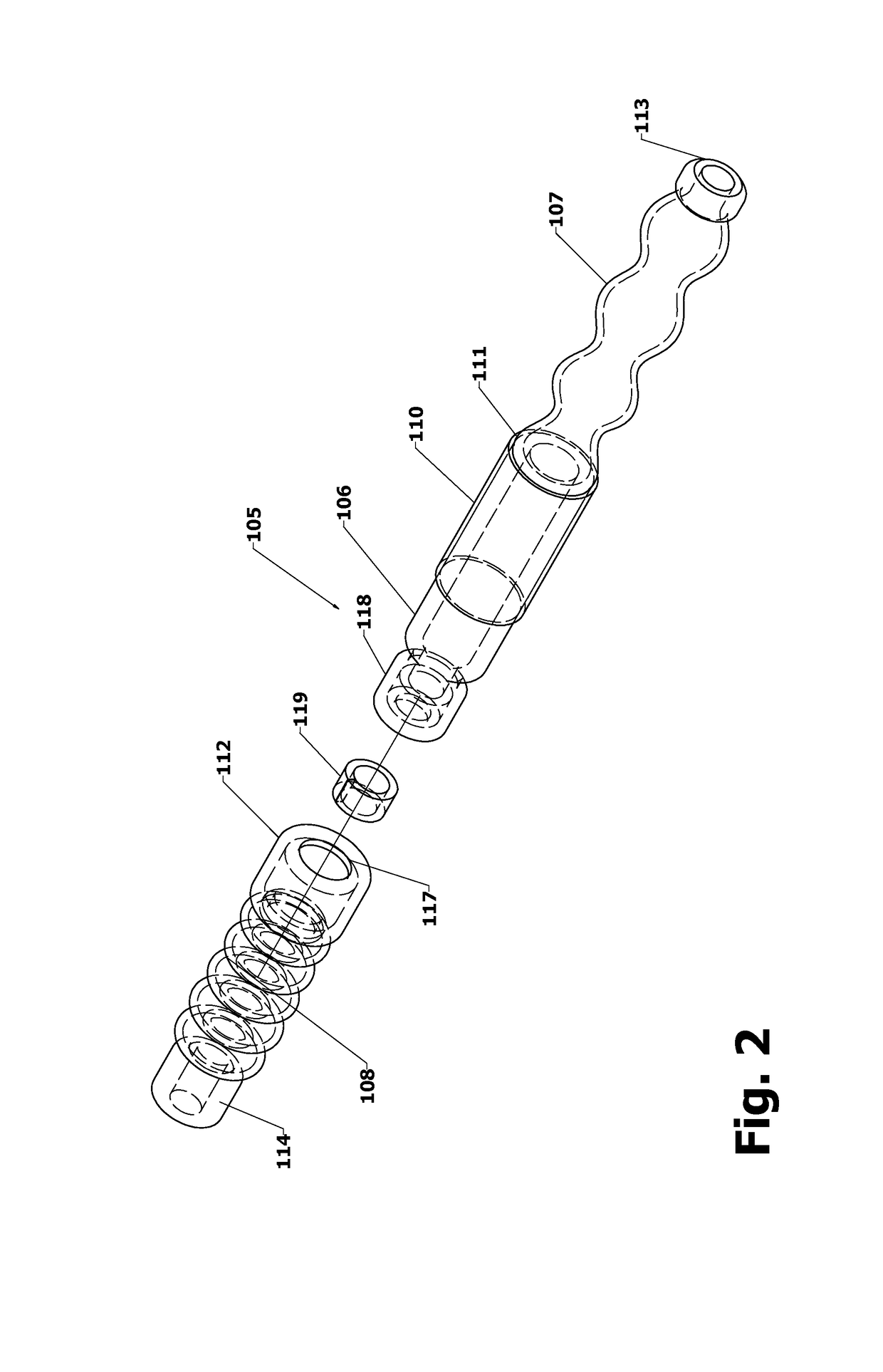
[0009]FIG. 1 illustrates the cross section of a preferred embodiment of the invention as applied to an implanted VAD driveline, and FIG. 2 shows the components comprising the inventive device. The driveline 100 powering the VAD (not shown) passes through a channel tunneled in the patient's subcutaneous tissue 101 and emerges from the skin 102. The driveline 100 comprises a cable 103 with a generally ci...


PUM


Abstract

The strain relief device of this invention reduces injury and danger of serious infection at driveline skin exit sites caused by routine patient activities and accidental stresses on the drivelines of ventricle assist devices and similar externally powered implanted medical devices. The device comprises a sleeve that forms an adherent biological interface with the skin and compliant seals between the sleeve and driveline. The compliant seals mechanically decouple linear and rotary driveline motions from the sleeve, while isolating the patients internal tissue from the outside environment. This mechanical decoupling reduces stresses and injury to the adherent interface, thereby reducing the risk of bacterial entry and infection. The device may be inserted into the patient as part of the driveline assembly implantation procedure, and is positioned such that the skin contacts and adheres to the outer diameter of the sleeve. It may also be partially or completely replaced or retrofitted to previously implanted drivelines in a relatively simple procedure.

Description

FIELD OF THE INVENTION[0001]The present invention is related to cables or “drivelines” connecting an external power supply to a medical device such as a ventricular assist device (VAD) implanted within a patient's body. More generally, it is related to methods and devices for reducing injury and infection at an exit site where a cable or tube passes through the patient's skin.BACKGROUND OF THE INVENTION[0002]Implanted VAD systems comprise an implanted pump that takes over at least part of a damaged heart's pumping function to improve the patient's ability to carry out the tasks of daily life. They may be used as temporary bridges to a heart transplant for periods of weeks to months or become permanent installations. In either case an electrical power cable or driveline is installed to connect to an external power supply and device controller. This driveline is tunneled through body tissue during the VAD implantation surgery, and exits through the skin. The driveline exit site in the...

Claims


Application Information

Patent Timeline
Patent Type & Authority Applications(United States)
IPC IPC(8): A61M1/10A61M60/178A61M60/857A61M60/88
CPCA61M1/1008A61M2205/0222A61M2205/0205A61M2025/0098A61M2205/0216A61M25/04A61M39/12A61M39/0208A61M60/857A61M60/88A61M60/178
Inventor MEACHAM, G.B. KIRBY
Owner MEACHAM G B KIRBY
Learn More