Method for Controlling an Hydraulically Actuated Shifting Element of a Vehicle Transmission

a technology of shifting element and transmission, which is applied in the direction of mechanical equipment, vehicle sub-unit features, transportation and packaging, etc., can solve the problems of affecting the quality of the gear shift in a negative way, faulty pressure control, etc., and achieve the effect of reducing the filling time and reducing the specified filling pressure of the shift elemen

Active Publication Date: 2018-10-25
ZF FRIEDRICHSHAFEN AG
View PDF0 Cites 0 Cited by
  • Summary
  • Abstract
  • Description
  • Claims
  • Application Information

AI Technical Summary

Benefits of technology

[0019]If the pressure compensating cavity is insufficiently filled, the specified filling pressure of the shift element can be reduced. The specified filling pressure is used for the initial filling of the pressure chamber without the shift element being engaged. At the end of the filling phase, the pressure chamber should be filled and the air gap of the shift element should have been overcome, and therefore the engagement process of the shift element can subsequently begin. During the filling phase, the shift element should effect no significant torque transmission. If the pressure compensating cavity is insufficient filled in the filling phase, the pressure increase in the pressure chamber induced by the centrifugal force cannot or cannot completely be compensated for. By way of an appropriate reduction of the filling pressure, the centrifugal force pressure increase contributes to the correct filling pressure. Therefore, an undesirably early torque transmission of the shift element can also be avoided when the pressure compensating cavity is empty or has been partially drained.
[0020]If the pressure compensating cavity is insufficiently filled, the filling time can be reduced. As a result, an undesirably early torque transmission of the shift element can also be avoided when the pressure compensating cavity is empty or partially empty.

Problems solved by technology

Proceeding from the inactive state, if a pressure chamber for actuating a shift element is to be filled for a short time, a faulty pressure control may occur if the pressure compensating cavity is not yet filled or is filled with only a small amount of hydraulic fluid.
This influences the quality of the gear shift in a negative way.

Method used


Image

  • Method for Controlling an Hydraulically Actuated Shifting Element of a Vehicle Transmission
  • Method for Controlling an Hydraulically Actuated Shifting Element of a Vehicle Transmission
  • Method for Controlling an Hydraulically Actuated Shifting Element of a Vehicle Transmission

Examples


Embodiment Construction

[0028]Reference will now be made to embodiments of the invention, one or more examples of which are shown in the drawings. Each embodiment is provided by way of explanation of the invention, and not as a limitation of the invention. For example, features illustrated or described as part of one embodiment can be combined with another embodiment to yield still another embodiment. It is intended that the present invention include these and other modifications and variations to the embodiments described herein.

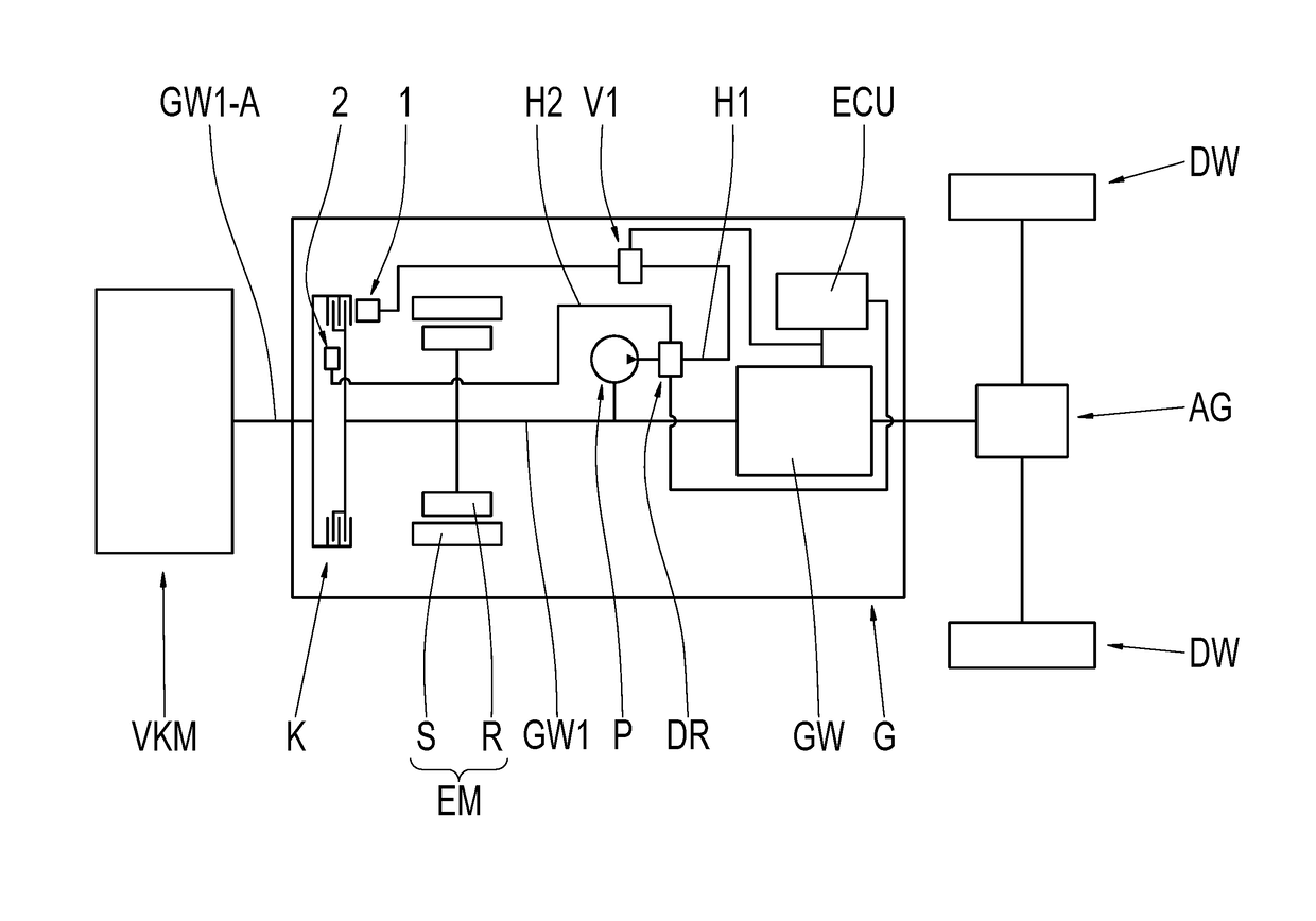
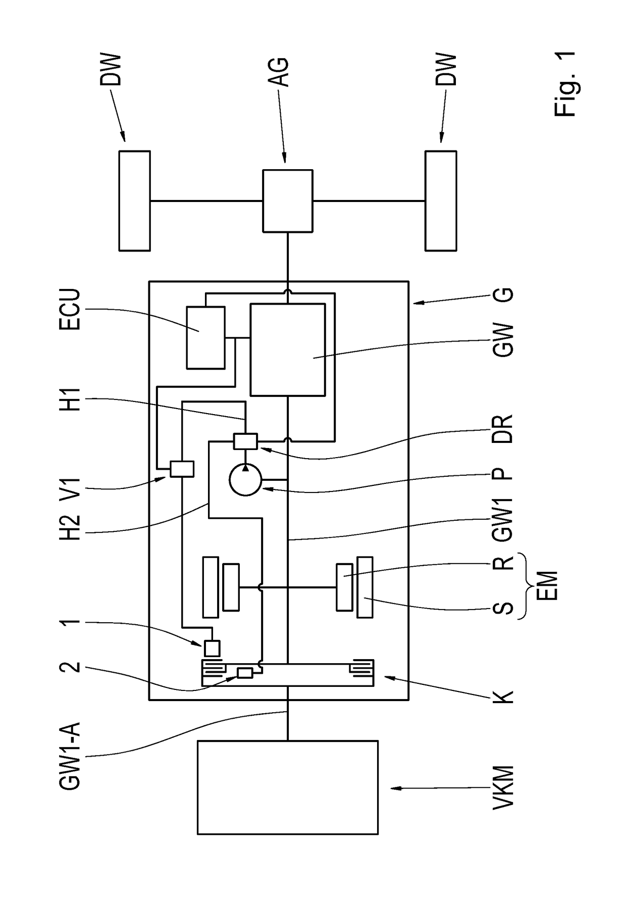
[0029]FIG. 1 schematically shows a drive train of a motor vehicle. An internal combustion engine VKM can be connected, via a clutch K, to a rotor R of an electric motor or machine EM. The electric machine EM, which includes not only the rotor R but also a rotationally fixed stator S, and the clutch K are part of a motor vehicle transmission G. The connection of the internal combustion engine VKM to the motor vehicle transmission G takes place at an external interface GW1-A of the ...


PUM


Abstract

A method for controlling a hydraulically actuated shift element of a vehicle transmission (G) includes determining a fill level of a pressure compensating cavity (2) associated with a pressure chamber (1) and controlling pressurizing of the pressure chamber (1) with hydraulic fluid based at least in part on the determined fill level of the pressure compensating cavity (2). The pressure chamber (1) is fillable with the hydraulic fluid by an electronically controlled hydraulic system in order to actuate the shift element.

Description

FIELD OF THE INVENTION[0001]The invention relates generally to a method for controlling a hydraulically actuated shift element of a vehicle transmission, and to a vehicle transmission with an appropriate control.BACKGROUND[0002]Unexamined patent application DE 34 36 190 A1 describes a method for the electronic control of an automatic vehicle transmission, wherein electrohydraulically actuatable friction elements bring about the shifting between the various transmission ratio steps. A variable characterizing the gear shift, for example the slip time, the shift time, or the speed gradient during the slip time, is compared with a reference variable, wherein a correction value is stored if a predefined deviation is exceeded. This correction value acts in a correcting manner for subsequent gear shifts. In this way, manufacturing related deviations or aging effects are to be compensated for.[0003]Patent U.S. Pat. No. 5,434,779 A describes a pressure control for an automatic transmission, ...

Claims


Application Information

Patent Timeline
Patent Type & Authority Applications(United States)
IPC IPC(8): F16H61/06F16D25/12
CPCF16H61/061F16D25/123F16H2061/062B60Y2400/416F16D2500/1045F16D2500/3024F16D2500/1024F16H2061/0087
Inventor MAYER, FLORIANDEPREZ, FRANK
Owner ZF FRIEDRICHSHAFEN AG
Why Eureka
Try Eureka