
Insertable fastener installation apparatus and method

a technology of insertable fasteners and installation apparatuses, which is applied in the direction of programme-controlled manipulators, counter-pressure devices, manufacturing tools, etc., can solve the problems of removing the protection of machine operators, machine operators can be hurt, and injuries can occur, so as to reduce labor and the movement of operators

Active Publication Date: 2018-11-01
STAFAST PROD
View PDF11 Cites 10 Cited by
  • Summary
  • Abstract
  • Description
  • Claims
  • Application Information

AI Technical Summary

Benefits of technology

The invention is an automated work insertable fastener installation apparatus that eliminates the need for an operator to physically install fasteners. This decreases safety risks and increases consistency and reliability in production. The apparatus requires only one or two operators to load and unload components, reducing labor costs. Furthermore, the apparatus offers ergonomic benefits by reducing the labor and movements required by operators in manipuring the substrate.

Problems solved by technology

However, when these machines are misused injuries can occur.
Doing so removes the machine operator's protection and there have been instances where the machine operator gets hurt.
These injuries are expensive because of increased workers' compensation insurance, settlements, OSHA fines, downtime, lost production, etc.
Along with financial loses, the machine operator can experience severe pain, broken bones, lacerations, reduction in dexterity, amputation, etc.
Another issue is high employee turnover rates.
This makes it difficult for them to keep employees who are properly trained.
Also, production rates fluctuate greatly because of inconsistent employee turnout.
The uncertainty of having employees show up to work is frustrating and can create financial losses.

Method used


Image

  • Insertable fastener installation apparatus and method
  • Insertable fastener installation apparatus and method
  • Insertable fastener installation apparatus and method

Examples


Embodiment Construction

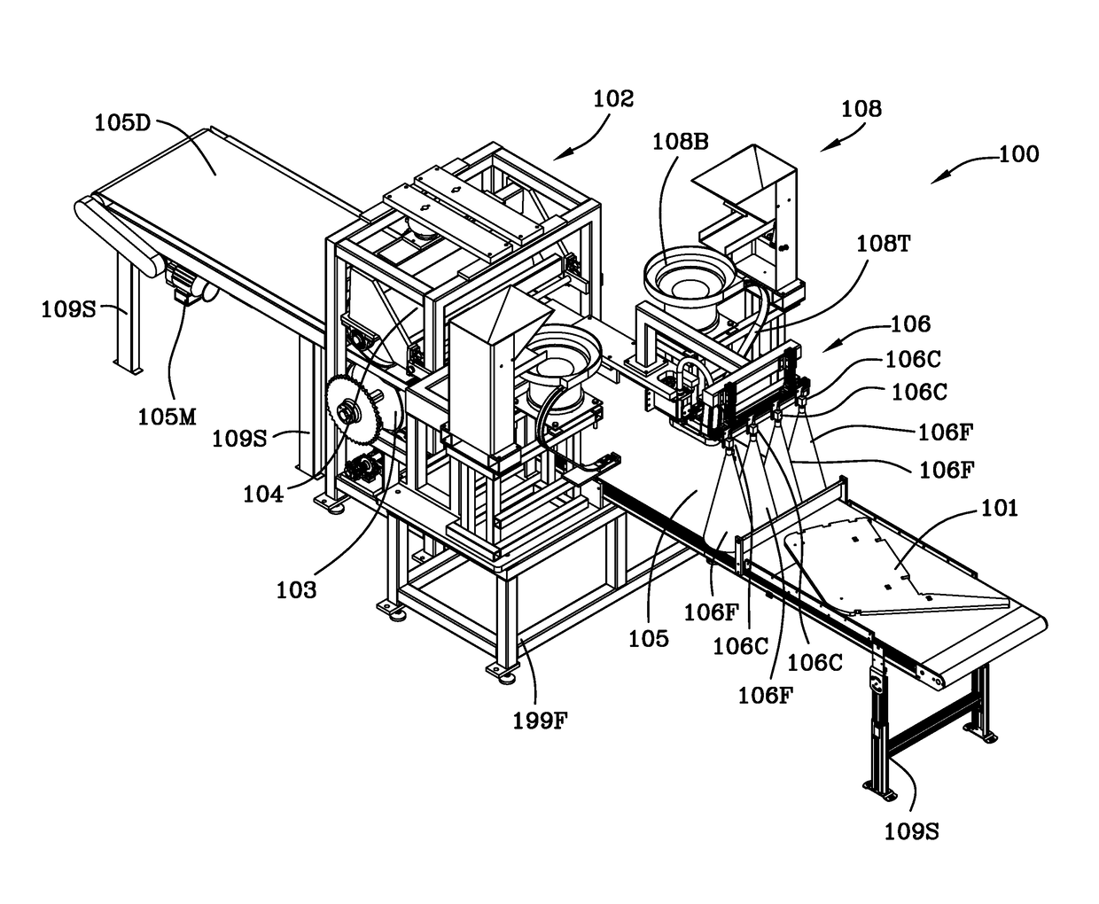
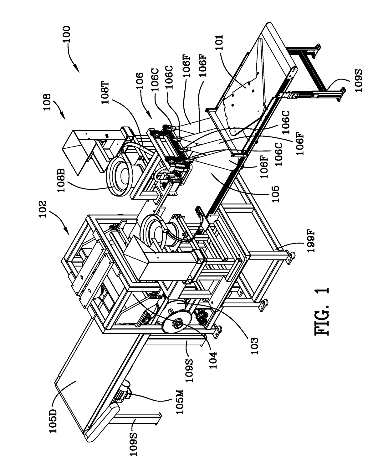
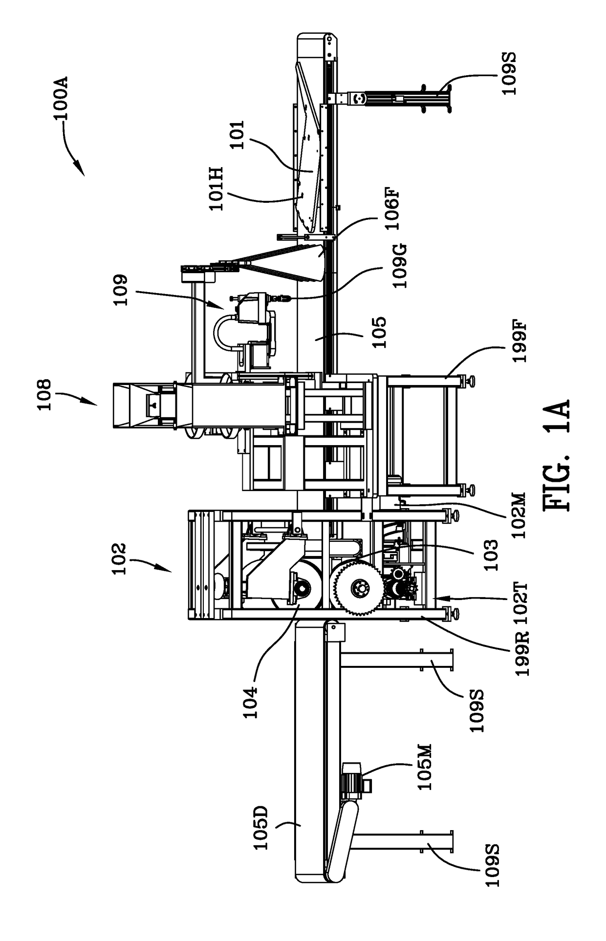
[0045]The insertable fastener installation apparatus utilizes the following components: conveyors, a vision system comprising an optical camera, a 4 Axis SCARA robot, one or more T-nut feed stations, a roller press station (or hydraulic press station (not shown)), and an electronically monitored safety enclosure.

[0046]A long conveyor belt (roughly 19′ in length) feeds through the insertable fastener installation apparatus. There is a safety enclosure through which a first portion of the conveyor passes and through which a second portion of the conveyor passes. An entrance passageway and an exit passageway in the safety enclosure passageway allow the components on the conveyor belt to freely enter and exit the safety enclosure of the insertable fastener installation apparatus freely. There are no other continuously accessible openings in the insertable fastener installation apparatus. There are electronically monitored access doors that terminate the operation of the insertable faste...


PUM

PropertyMeasurementUnit
thicknessesaaaaaaaaaa
diameteraaaaaaaaaa
diameteraaaaaaaaaa

Abstract

An insertable fastener installation apparatus for a flat substrate has a thickness, T. A roller press station is used to press T-nuts into holes in the substrate. An optical vision system detects the location of the holes in the moving substrate and aligns the t-nuts with the holes. A computer controlled pick and place robot takes T-nuts from an escapement of a hopper feed system and aligns, but does not fully insert, the t-nuts in the substrate. A conveyor system feeds the substrates through the optical vision system, the pick and place robot station and the roller press station. A first roller is spaced apart from a second roller by a gap in the roller press station and the gap is less than the thickness of the substrate. The hopper feed system includes a bulk hopper, a bowl, a track and an escapement.

Description

[0001]This patent application claims the benefit of and the priority to U.S. provisional patent application Ser. No. 62492768 filed May 1, 2017, This patent application incorporates U.S. provisional patent application Ser. No. 62492768 filed May 1, 2017 herein in its entirety by reference hereto.FIELD OF THE INVENTION[0002]The invention is in the field of installing insertable fasteners in substrates wherein the substrates are selected from the group consisting of wood, plywood, chipboard, oriented strand board, frame grade plywood, and plastic and the insertable fastener does not require deformation or rotation.BACKGROUND OF THE INVENTION[0003]Existing T-nut insertion machines use a human operator that places a component into the machine, locates the pre-drilled pilot hole, pushes down to depress a safety switch, and steps on a foot pedal. Once this is done, a pneumatic cylinder drives a T-nut downward at high velocity and pressure, installing it into the component. These machines,...

Claims


Application Information

Patent Timeline
Patent Type & Authority Applications(United States)
IPC IPC(8): B23P19/10B23P19/00B23P19/12B23P19/06
CPCB23P19/105B23P19/006B23P19/12B23P19/06B23P19/004B23P19/062Y10T29/53039Y10T29/53052Y10T29/5343Y10T29/49833B21B29/00B23P19/064B25J9/0093B25J9/0096B25J9/1687B25J9/1697
Inventor DIETER, JONATHAN WAYNE
Owner STAFAST PROD
Learn More