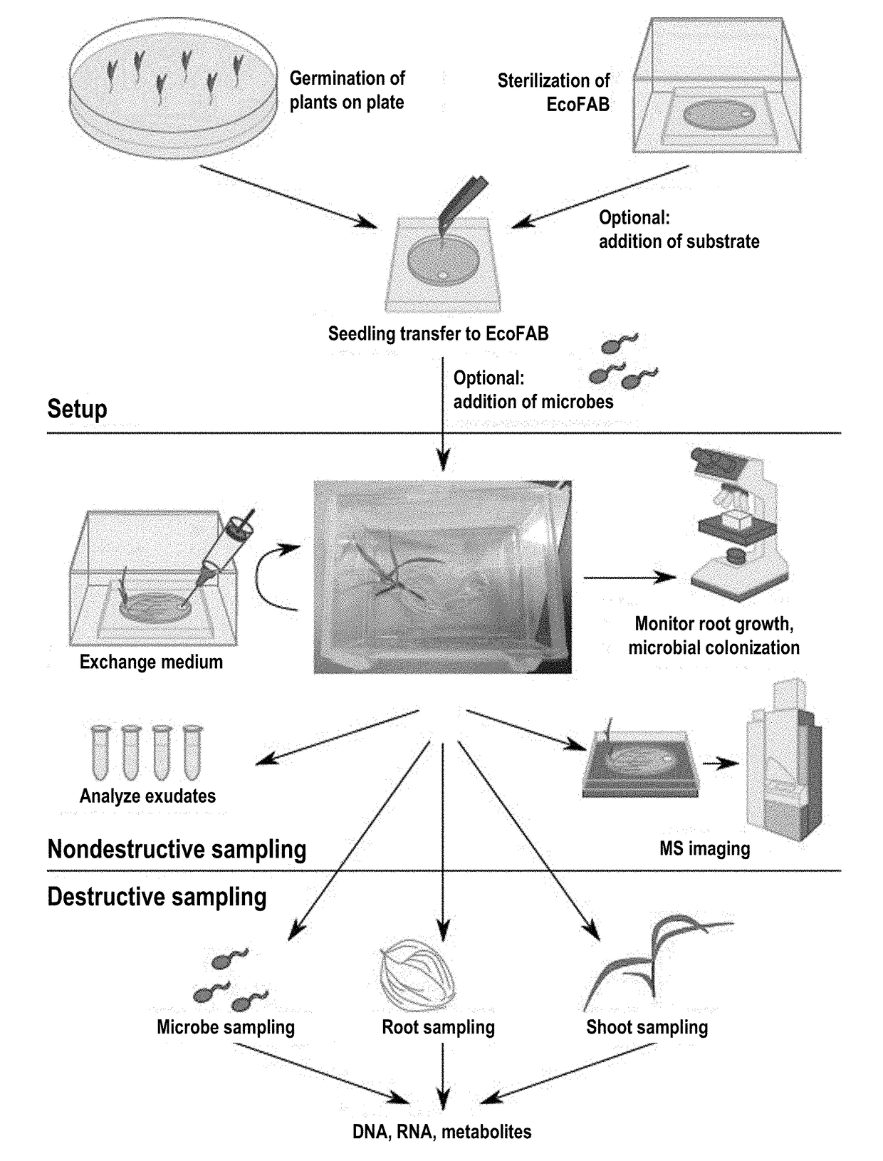
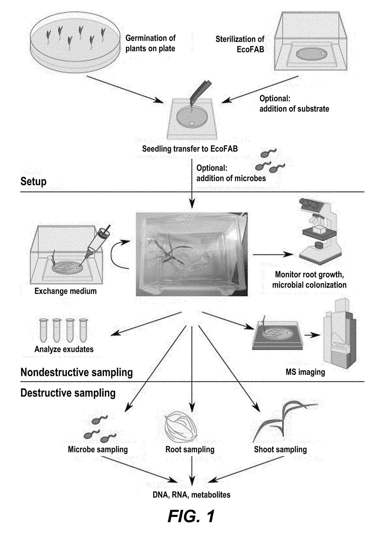
Ecosystem for determining plant-microbe interactions
a plant-microbe and ecosystem technology, applied in the field of ecological processes, can solve the problems of lacking vital understanding of the interaction between plant-microbes and soil in the rhizospher
- Summary
- Abstract
- Description
- Claims
- Application Information
AI Technical Summary
Benefits of technology
Problems solved by technology
Method used
Image
Examples
example 1
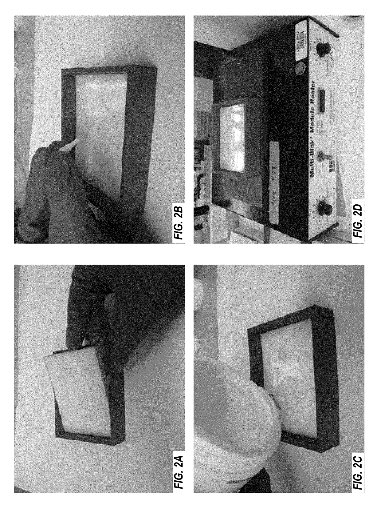
[0091]This example demonstrates casting PDMS layers for plant growth systems.
Materials and Equipment
[0092]1. 3D printed mold, plug, and casting tray (STL files available from Northen Lab)
[0093]2. PDMS: Dow Corning Sylgard 184 Silicone Elastomer Clear Kit (Ellsworth Adhesives)
[0094]3. Vacuum chamber
[0095]4. Hot plate / heating block
[0096]5. Compressed gas duster
[0097]6. Utility knife
Protocol 1. Plant Growth Device Fabrication: Casting PDMS Layers
[0098]1.1. Measure out and pour 40 mL of PDMS elastomer base into a mixing container. Each layer uses ˜40 mL of elastomer base. To make more or less layers per batch, adjust volume used accordingly.
[0099]1.2. Add 4 mL of elastomer curing agent to form a 10:1 ratio of base to curing agent. A 30:1 ratio will make a softer, stickier layer that can be reversibly adhered to glass. A 5:1 ratio will make a harder, less-adhesive layer that can be used in conjunction with a clamp and reversely bond to a NIMS chip. Mix gently with a st...
example 2
Bonding PDMS Layers to Microscope Slides
[0115]This example demonstrates bonding PDMS layers to microscope slides.
Materials and Equipment
[0116]1. Microscope glass slides (3″×2″ for small plant growth devices, 4″×3¼″ for large plant growth devices)
[0117]2. Baking oven (for sterilization)
[0118]3. Plasma Cleaner (Harrick Plasma, Model PDC-001)
[0119]4. Hot plate / heating block
Protocol 2. Plant Growth Device Fabrication: Chemically Attaching PDMS Layers onto Microscope Slides
[0120]2.1. Wash glass slides with warm soap and milli-Q filtered water.
[0121]2.2. Bake glass slides at 400° C. for 1 hour to sterilize and remove trace compounds.
[0122]2.3. With scissors or utility knife, cut the PDMS layer to fit the glass slide (3″33 2″ for the small size, 4″ by 3¼″ for the large size). Even if the large sized PDMS fits on the large glass slide without trimming, still trim off the edges of the PDMS. The edges often have a raised lip from being cast, and this lip will prevent PDMS from making complete...
example 3
Molds
[0134]This example demonstrates molds for making the PDMS layers.
[0135]FIGS. 4A-4C show two molds of plant growth devices. FIG. 4A shows a non-limiting exemplary layout of the mold. The removable plug can be removed after the PDMS has been poured and cured, creating a reservoir for the plant shoot to grow out of. FIG. 4B shows the standard mold, on the left, has narrow inlet and outlet ports, while the variant mold on the left has a wide outlet port. The standard mold allows for users to connect flow pumps directly to the plant growth device for precise fluidic control. The variant mold on the left can be helpful when the user wishes to collect root exudates by hand with a pipette or syringe. FIG. 4C shows molds in two sizes. The larger left mold creates a 5 mL root chamber, while the right mold creates a 2 mL root chamber.
[0136]Altogether, this example shows molds each with a base piece and a side piece for easy separation of the PDMS layer from the mold.
PUM
| Property | Measurement | Unit |
|---|---|---|
| volume | aaaaa | aaaaa |
| diameter | aaaaa | aaaaa |
| volume | aaaaa | aaaaa |
Abstract
Description
Claims
Application Information
 - R&D
- Intellectual Property
- Life Sciences
- Materials
- Tech Scout
- Unparalleled Data Quality
- Higher Quality Content
- 60% Fewer Hallucinations
Browse by: Latest US Patents, China's latest patents, Technical Efficacy Thesaurus, Application Domain, Technology Topic, Popular Technical Reports.
© 2025 PatSnap. All rights reserved.Legal|Privacy policy|Modern Slavery Act Transparency Statement|Sitemap|About US| Contact US: help@patsnap.com


