Plasma control apparatus

a control apparatus and plasma technology, applied in the direction of plasma technique, electrical apparatus, electric discharge tube, etc., can solve the problems of inability to perform plasma processing such as etching with inability to achieve high accuracy and stability, high-speed impedance matching, and stable control of voltage and curren

Active Publication Date: 2018-11-01
SUMITOMO PRECISION PROD CO LTD
View PDF0 Cites 8 Cited by
  • Summary
  • Abstract
  • Description
  • Claims
  • Application Information

AI Technical Summary

Benefits of technology

[0050]The plasma control apparatus according to the present invention enable high-speed impedance matching between a power source unit and plasma even when the impedance of the plasma changes with a chan

Problems solved by technology

This may result in a failure to perform the plasma processing such as etching with high accuracy and stability.
In addition, the mechanically driven way to perform the impedance matching between the power source unit 1′ and the plasma P involves a problem in that the matching cannot be performed at high speed.
This may result in a failure to perform the plasma processing such as etching with high accuracy and stability.
In addition, the mechanically driven way to perform the impedance matching between the power source unit 3′ and the plasma

Method used


Image

  • Plasma control apparatus
  • Plasma control apparatus
  • Plasma control apparatus

Examples


first embodiment

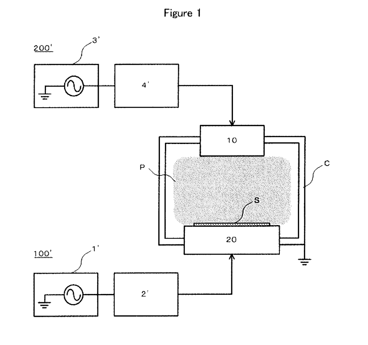
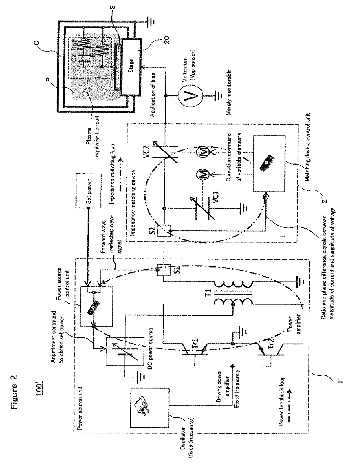
[0064]FIG. 5 is a schematic configuration diagram of a plasma control apparatus according to a first embodiment of the present invention.

[0065]As illustrated in FIG. 5, a plasma processing apparatus to which a plasma control apparatus 100 according to the first embodiment is applied has the following configuration. In other words, the plasma processing apparatus is an apparatus that includes a chamber C, an element 10 attached to an upper portion of the chamber C and configured to generate plasma P in the chamber C, and a stage 20 attached to a lower portion of the chamber C and allowing a substrate S to be placed thereon, and that uses the plasma P generated in the chamber C to subject the placed substrate S to processing using plasma such as etching. In a case where the plasma P is what is called inductively coupled plasma, a coil is used as the element 10, and in a case where the plasma P is what is called capacitively coupled plasma, an electrode disposed parallel to the stage 2...

second embodiment

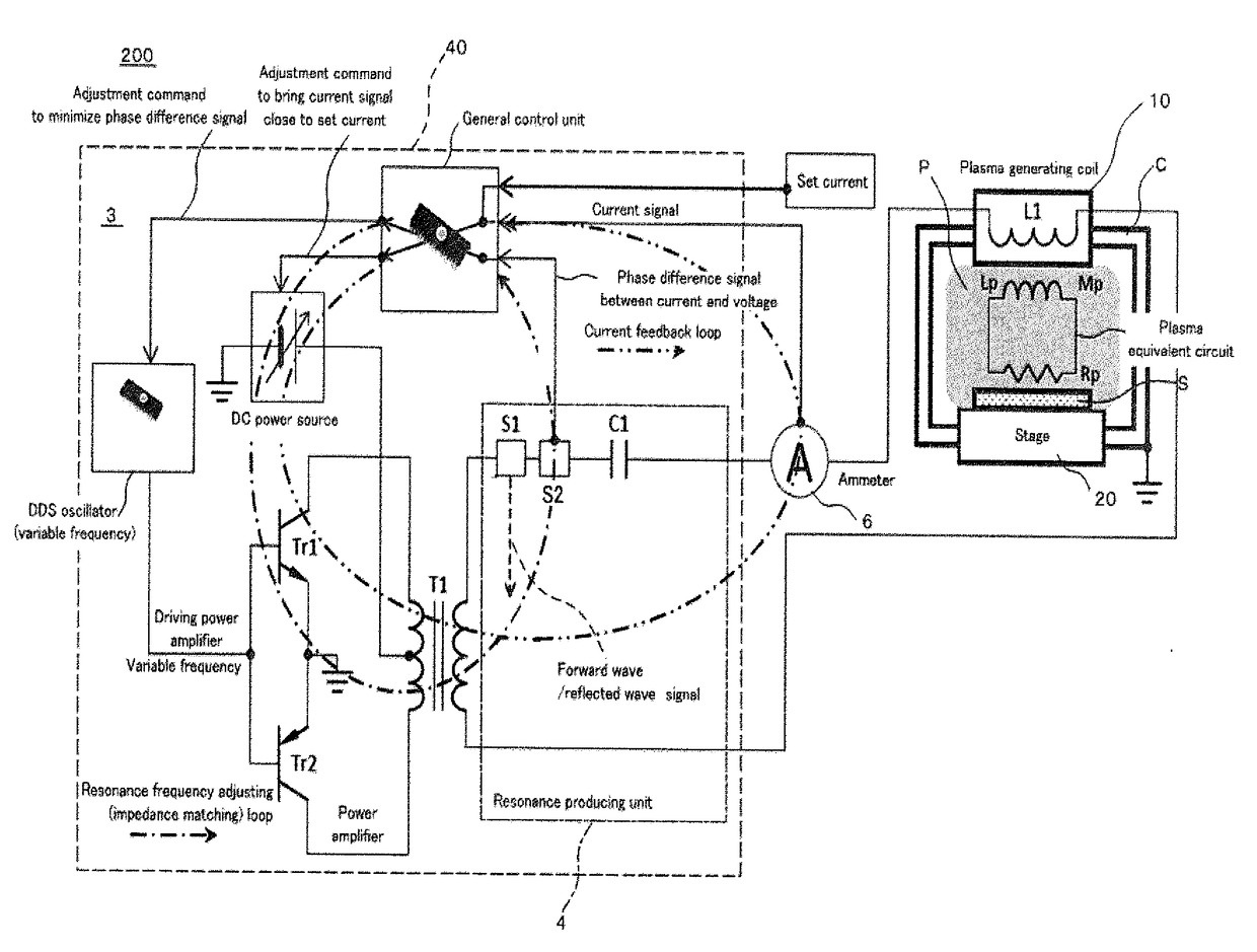
[0083]FIG. 7 is a schematic configuration diagram of a plasma control apparatus according to a second embodiment of the present invention.

[0084]As illustrated in FIG. 7, a plasma processing apparatus to which a plasma control apparatus 200 according to the second embodiment is applied has the same configuration as that of the plasma processing apparatus described in the first embodiment. However, in the plasma processing apparatus to which the plasma control apparatus 200 according to the second embodiment is applied, the plasma P is inductively coupled plasma, and a coil is used as the element 10.

[0085]The plasma control apparatus 200 according to the second embodiment is an apparatus that supplies radio-frequency power to an element (a plasma generating coil) 10 of a plasma processing apparatus having the above configuration. As illustrated in FIG. 7, the plasma control apparatus 200 includes a power source unit 3 configured to supply the radio-frequency power to the element 10, a...

third embodiment

[0098]FIG. 10 is a schematic configuration diagram of a plasma control apparatus according to a third embodiment of the present invention.

[0099]As illustrated in FIG. 10, a plasma processing apparatus to which a plasma control apparatus 200A according to the third embodiment is applied has the same configuration as those of the plasma processing apparatus described in the first and second embodiments. However, in the plasma processing apparatus to which the plasma control apparatus 200A according to the third embodiment is applied, the plasma P is capacitively coupled plasma, and an electrode is used as the element 10.

[0100]The plasma control apparatus 200A according to the third embodiment is an apparatus that supplies radio-frequency power to an element (a plasma generating electrode) 10 of a plasma processing apparatus having the above configuration. As illustrated in FIG. 10, the plasma control apparatus 200A includes a power source unit 3A configured to supply the radio-frequen...


PUM


Abstract

A plasma control apparatus includes a power source unit, a resonance producing unit, and a voltmeter. The resonance producing unit includes an LC circuit formed by a coil L1 and a capacitor C1 connected to each other, and a sensor S2 configured to detect a phase difference between current flowing in and voltage applied to the LC circuit, and the capacitor C1 of the LC circuit has a capacitance larger than an expected capacitance of the plasma P. The power source unit 1 configured to control the magnitude of radio-frequency power to be supplied in such a manner as to bring the voltage measured with the voltmeter 5 close to a set voltage as a target, and controls the frequency of the radio-frequency power to be supplied in such a manner as to minimize the phase difference detected with the sensor S2.

Description

TECHNICAL FIELD[0001]The present invention relates to a plasma control apparatus that supplies radio-frequency power to a plasma processing apparatus for performing processing using plasma such as etching on a substrate. The present invention particularly relates to a plasma control apparatus that enables high-speed impedance matching between a power source unit and plasma even when the impedance of the plasma changes with a change in state of the plasma, and can perform processing using plasma with high accuracy and stability by achieving stable control over voltage and current, which is important in the processing using plasma.BACKGROUND ART[0002]A plasma processing apparatus that includes, as illustrated in FIG. 1, a chamber C, an element 10 attached to an upper portion of the chamber C and configured to generate plasma P in the chamber C, and a stage 20 attached to a lower portion of the chamber C and allowing a substrate S to be placed thereon, and that uses the plasma P genera...

Claims


Application Information

Patent Timeline
IPC IPC(8): H01J37/32H01L21/67H03H7/38
CPCH01J37/32183H01L21/67069H03H7/38H01J37/321H01J37/32091H01J2237/24564H01J2237/334H01J2237/332H01L21/3065H05H1/46H01J37/32082H01J37/32146H01J37/32155H01J37/32174H01J37/3299
Inventor HAYAMI, TOSHIHIROFUJII, RYOSUKE
Owner SUMITOMO PRECISION PROD CO LTD
Why Eureka
Try Eureka