Phase compensation method for power factor correction circuit

Active Publication Date: 2018-11-01
DELTA ELECTRONICS (THAILAND) PUBLIC CO LTD
View PDF1 Cites 4 Cited by
  • Summary
  • Abstract
  • Description
  • Claims
  • Application Information

AI Technical Summary

Benefits of technology

The present invention offers a way to improve the performance of a power factor correction circuit in a more effective way. This method helps to reduce distortion, decrease harmonic distortion, and increase power factor.

Problems solved by technology

If the power factor is lower than 1, the transmitted power possibly loses because of phase mismatch between the current and the voltage or noise.
Consequently, the power factor is increased, and the total harmonic distortion is increased.
However, the conventional power factor correction circuit still has some drawbacks.
Consequently, the total harmonic distortion increases, and the power factor decreases.

Method used


Image

  • Phase compensation method for power factor correction circuit
  • Phase compensation method for power factor correction circuit
  • Phase compensation method for power factor correction circuit

Examples


Embodiment Construction

[0014]The present invention will now be described more specifically with reference to the following embodiments. It is to be noted that the following descriptions of preferred embodiments of this invention are presented herein for purpose of illustration and description only. It is not intended to be exhaustive or to be limited to the precise form disclosed.

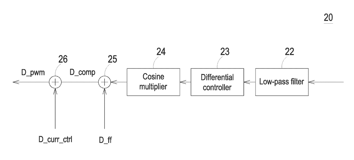
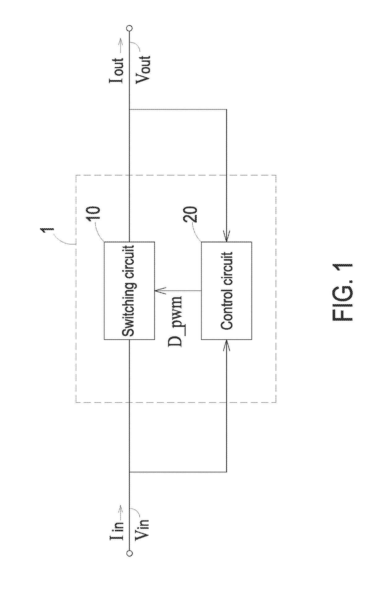
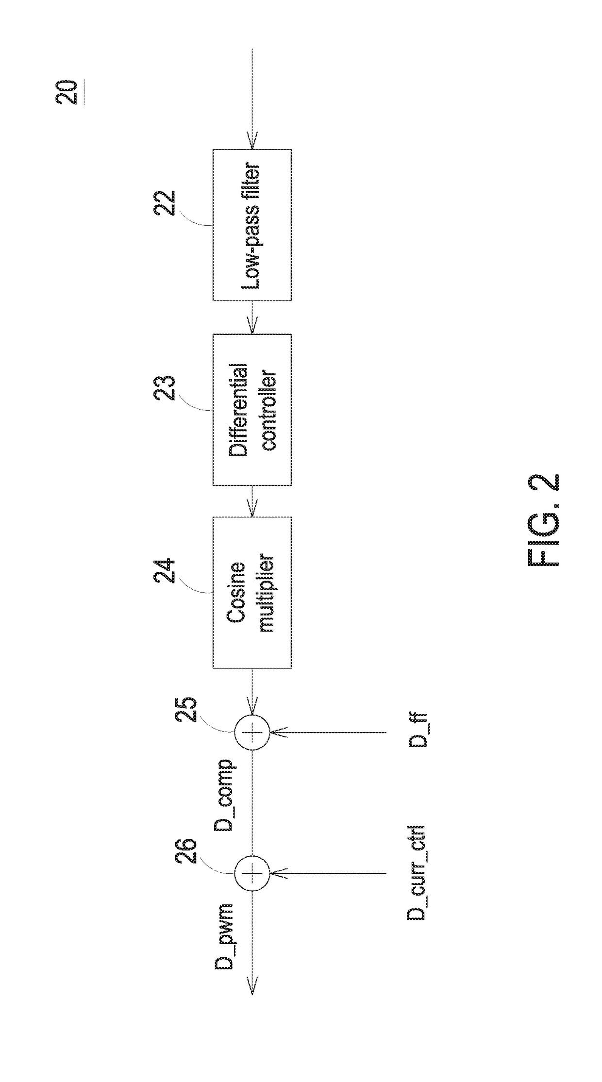
[0015]FIG. 1 is a schematic circuit diagram illustrating the architecture of a power factor correction circuit according to an embodiment of the present invention. The power factor correction circuit 1 can be applied to a power converter (not shown) in order to increase the power factor of the power converter. The power factor correction circuit 1 receives an input current Iin and an input voltage Vin and generates an output current Iout and an output voltage Vout. The power factor correction circuit 1 comprises a switching circuit 10 and a control circuit 20. By alternately turning on or turning off the switching circuit 10, the...


PUM


Abstract

A method for phase compensating a power factor correction circuit is provided. Firstly, a present current value of an input current is sampled, and the sampled signal is filtered. Then, a present waveform of the input current corresponding to the present current value of the filtered sampled signal and a previous waveform of the input current corresponding to a previous current value of the filtered sampled signal are predicted, and a current error signal is generated according to a difference between the present waveform and the previous waveform. Then, the current error signal is adjusted, and an adjusted signal is generated. Then, a feedforward signal is added to the adjusted signal, and a phase compensation signal. Then, a current control signal is added to the phase compensation signal, and a pulse width modulation signal is generated to control a switching circuit.

Description

FIELD OF THE INVENTION[0001]The present invention relates to a phase compensation method, and more particularly to a phase compensation method for a power factor correction circuit.BACKGROUND OF THE INVENTION[0002]Generally, the load for a power converter has diversified forms. For example, the load includes a resistive impedance, an inductive impedance, a capacitive impedance, or a combination thereof. When the input current to the load and the input voltage to load are in phase, the power factor is close to 1. If the power factor is lower than 1, the transmitted power possibly loses because of phase mismatch between the current and the voltage or noise.[0003]For avoiding the power factor reduction and increasing the power transmission efficiency, the conventional power converter has a power factor correction function. For example, the conventional power converter is usually equipped with an active type power factor correction circuit to achieve the power factor correction function...

Claims


Application Information

Patent Timeline
IPC IPC(8): H02M1/42G05F1/70H02P23/26
CPCH03D3/001H03D3/02H02P23/26G05F1/70H02M1/4208Y02B70/10Y02P80/10
Inventor BEINLICH, DOMINIK REINHARD
Owner DELTA ELECTRONICS (THAILAND) PUBLIC CO LTD
Why Eureka
Try Eureka