Unlock instant, AI-driven research and patent intelligence for your innovation.
System and method for maintaining high speed communication
Active Publication Date: 2018-11-01
SAMSUNG DISPLAY CO LTD
View PDF0 Cites 10 Cited by
Summary
Abstract
Description
Claims
Application Information
AI Technical Summary
This helps you quickly interpret patents by identifying the three key elements:
Problems solved by technology
Method used
Benefits of technology
Benefits of technology
The present patent is about a system and method for determining the locking phase in a data communication system. The system includes a transmitter, a data communication channel, and a receiver. The receiver includes a CDR phase detector that calculates the overall pulse response of the system and obtains a function value for each phase corresponding to a resolution per symbol. The function value is set to be the minimum value of the function at a specific phase. The receiver also includes a continuous time linear equalizer, a decision-feedback equalizer, and a deserializer to process the data received over the channel. The technical effect of this patent is to improve the accuracy and reliability of data communication systems by accurately locking the CDR phase and ensuring the data is transmitted and received correctly.
Problems solved by technology
This motivates the use of advanced equalization schemes at both transmitter and receiver ends, whose optimal operation has been a constant challenge from both communication and circuit design standpoints.
Method used
Image
Click on the blue label to locate the original text in one second.
Reading with bidirectional positioning of images and text.
Examples
first embodiment
[0044]FIG. 3 displays a flow diagram illustrating the present disclosure.
[0045]The flow diagram in FIG. 3 is based on the following equations Eq. 1-1, Eq. 1-2 and Eq. 1-3:
[0046]Each of the variables of the equations above, as well as the equations that follow, can be defined as follows:[0047]d[n]: the nth transmit bit[0048]Nph: the phase interpolator / simulation resolution per symbol[0049]i ∈ [1, Nph]: a phase within the range of PI / simulation resolution[0050]yn[i]: signal amplitude corresponding to d[n], at an arbitrary phase i ∈ [1, Nph][0051]h: the overall pulse response of the channel[0052]hi: the overall impulse response at phase i ∈ [1, Nph][0053]ixing: CDR crossing phase[0054]ilock: CDR locking phase
[0055]As can be seen above, according to some example embodiments of the present disclosure, the locking phase is realized when t...
fourth embodiment
[0103]FIG. 7 displays a flow diagram illustrating the present disclosure.
[0104]The flow diagram is based on the following equations Eq. 8-1, Eq. 8-2, Eq. 8-3, Eq. 8-4 and Eq. 8-5:
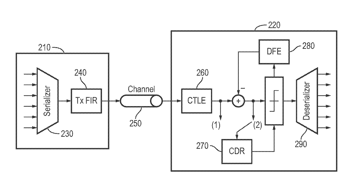
[0105]According to the embodiment shown in FIG. 7, the high speed link incorporates a majority voting logic. Also, the CDR phase detector 270 samples data after the DFE 280, which sampling point is indicated as (2) in FIG. 2. This arrangement results in CDR phase detector 270 interaction with DFE 280, which can impact the CDR locking phase.
[0106]The method, according to this embodiment, begins at Step 702 as shown in FIG. 7. In Step 702, the CDR phase de...
PUM
Abstract
A data communication system includes a transmitter, a channel, and a receiver includes a Clock and Data Recovery (CDR) phase detector that is configured to: calculate an overall pulse response of the data communication system; obtain a function value for each of a plurality of phases, the plurality of phases corresponding to a resolution per symbol; set a crossing phase to be a phase at which this value is minimum among the plurality of phase; and set the CDR locking phase to be the crossing phase plus a midpoint from among the plurality of phases.
Description
CROSS-REFERENCE TO RELATED APPLICATION(S)[0001]The present application claims priority to and the benefit of U.S. Provisional Patent Application No. 62 / 492,856 filed on May 1, 2017, the content of which is incorporated herein by reference in its entirety.BACKGROUND1. Field[0002]One or more aspects of embodiments disclosed herein relate to a system and method to determine the Clock and Data Recovery (CDR) locking phase in high speed links.2. Description of Related Art[0003]The ever increasing demand for higher data rates exacerbates Inter-Symbol Interference (ISI) caused by dispersive channels on high speed serial links. This motivates the use of advanced equalization schemes at both transmitter and receiver ends, whose optimal operation has been a constant challenge from both communication and circuit design standpoints. The most accurate approach to guarantee optimal operation of such systems is through analytical methods, which use the knowledge of the channel (typically measured)...
Claims
Application Information
Patent Timeline
Application Date:The date an application was filed.
Publication Date:The date a patent or application was officially published.
First Publication Date:The earliest publication date of a patent with the same application number.
Issue Date:Publication date of the patent grant document.
PCT Entry Date:The Entry date of PCT National Phase.
Estimated Expiry Date:The statutory expiry date of a patent right according to the Patent Law, and it is the longest term of protection that the patent right can achieve without the termination of the patent right due to other reasons(Term extension factor has been taken into account ).
Invalid Date:Actual expiry date is based on effective date or publication date of legal transaction data of invalid patent.

