Hollow weave airbag

a technology of airbags and weaves, applied in the field of airbags, can solve the problems of affecting the internal pressure maintaining performance of airbags, affecting the thickness and weight of airbags, and affecting the storability of airbags in some cases, so as to achieve the effect of improving the internal pressure maintaining performan

Active Publication Date: 2018-11-08
SUMISHO AIRBAG SYST CO LTD
View PDF10 Cites 1 Cited by
  • Summary
  • Abstract
  • Description
  • Claims
  • Application Information

AI Technical Summary

Benefits of technology

[0011]An object of the present invention is to provide an airbag in which by providing a twill-like structure area in which the part where a coating material easily permeates the inside of base fabric is continuously formed, in at least part of an outer region of an inflation part of a laminated hollow weave airbag, a shielding part for suppressing gas leak is arranged, gas leakage from a cut face is suppressed, and the internal pressure maintaining performance can be improved.Solution to Problem

Problems solved by technology

However, in a case of trying to obtain favorable internal pressure maintaining performance by such a method, it is required to increase the applying amount of a silicone resin, the thickness and the weight are increased, and the storability may be deteriorated in some cases.
In addition, it is known that in the outer peripheral joining part positioned on the outer periphery of an inflation part, weave shifting (yarn slippage) of the base fabric is easily generated at the time of inflation, and in a hollow weave airbag by silicone coating, the gas leakage generated from the yarn slippage point greatly affects the internal pressure maintaining performance of the airbag.
However, by suppressing the gas leakage from the yarn slippage in the outer peripheral joining part, gas leakage from a cut face is generated, and there has been a case where sufficient internal pressure maintaining performance is not obtained.
There have been no sufficient studies to cope with the gas leakage from a cut face of such a laminated hollow weave airbag.
However, in this literature, gas leakage from a cut face has not been considered, and it cannot be said that it is sufficient as a technique for suppressing gas leakage particularly from a laminated hollow weave airbag.

Method used


Image

  • Hollow weave airbag
  • Hollow weave airbag
  • Hollow weave airbag

Examples


example 1

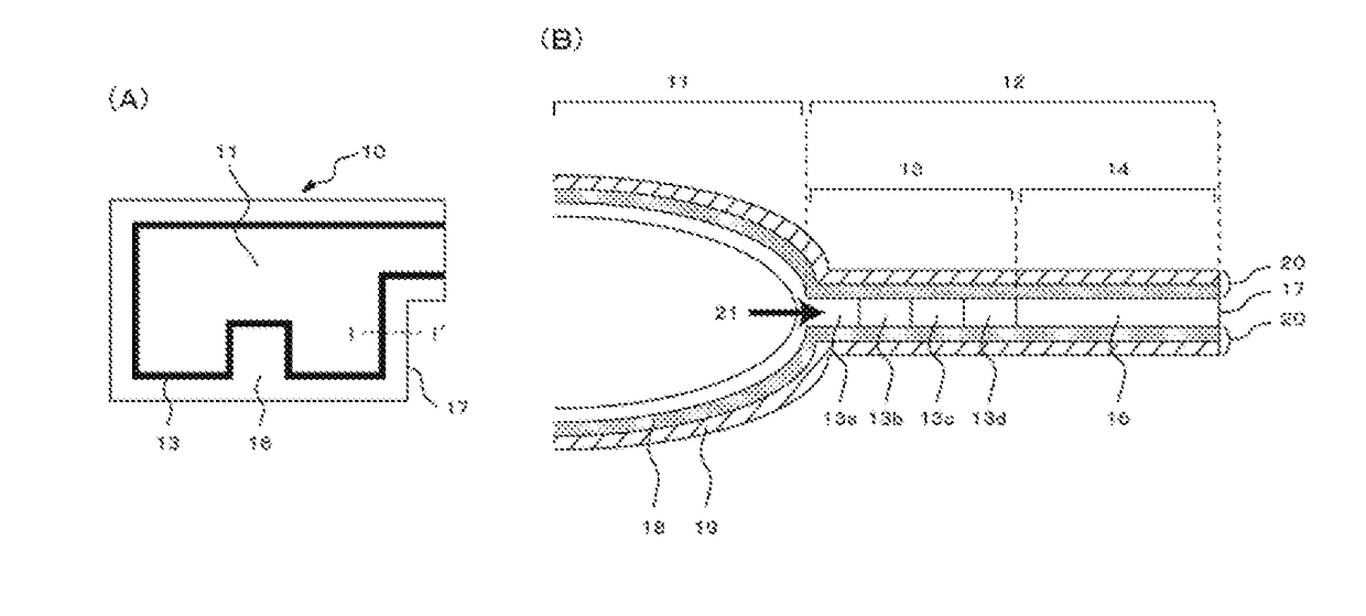
[0101]Yarns having a fineness of polyester raw yarn of 466 dtex and a single yarn number of 96, manufactured by Hailide, were sized with a sizing agent containing a water-soluble polyester as the main component, and used as warps. As wefts, the same polyester raw yarns as those of the warps were used. By using an air jet loom (manufactured by DORMER) equipped with a jacquard machine (manufactured by Staubli), an inflation part was made of a double plain weave, the weave for an outer peripheral joining part was made of a 2 / 2 basket weave (FIG. 13-A) (13a), a reversible figured double weave (FIG. 13-B) (13b), and a 3 / 3 basket weave (FIG. 13-C) (13c) in this order from the inflation part side, a 8-harness twill weave (FIG. 9-C) (15) was provided with a width of 12 mm in an outer edge part connected to the outer peripheral joining part, and hollow weave base fabric was weaved so that the finished density is 57 warps / 2.54 cm, and 49 wefts / 2.54 cm.

[0102]The woven hollow weave base fabric ...

example 2

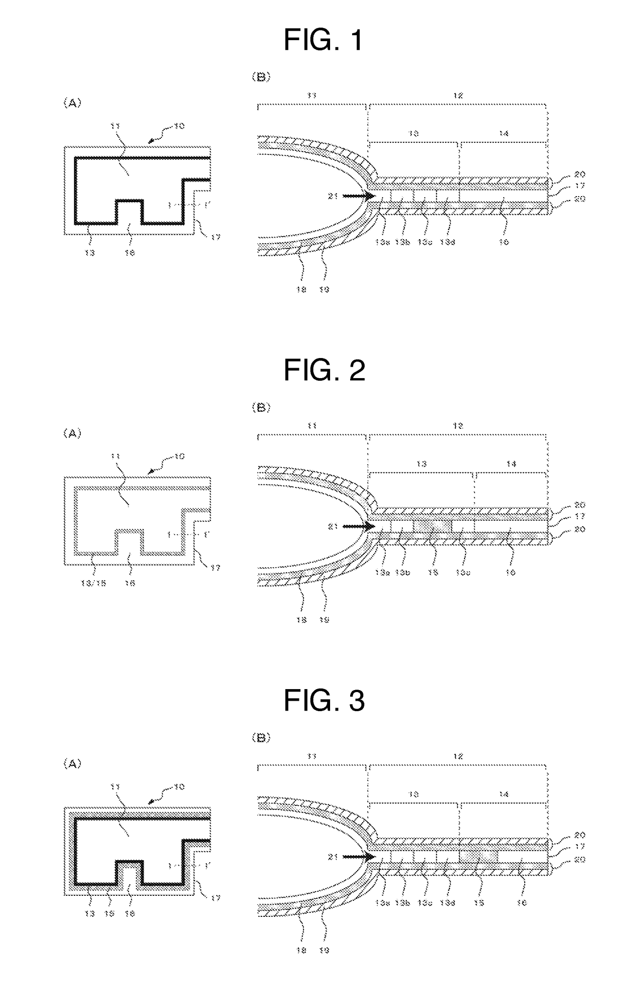
[0105]The weave for an outer peripheral joining part was made of a 2 / 2 basket weave (FIG. 13-A) (13a), a reversible figured double weave (FIG. 13-B) (13b), and a 3 / 3 basket weave (FIG. 13-C) (13c) in this order from the inflation part side, and hollow weave base fabric was prepared in accordance with the manner of Example 1 except that the weaving was performed by providing a pointed twill weave (FIG. 9-I) (15) with a width of 12 mm in an outer edge part spaced apart from the outer peripheral joining part.

[0106]The evaluation results are shown in TABLE 1.

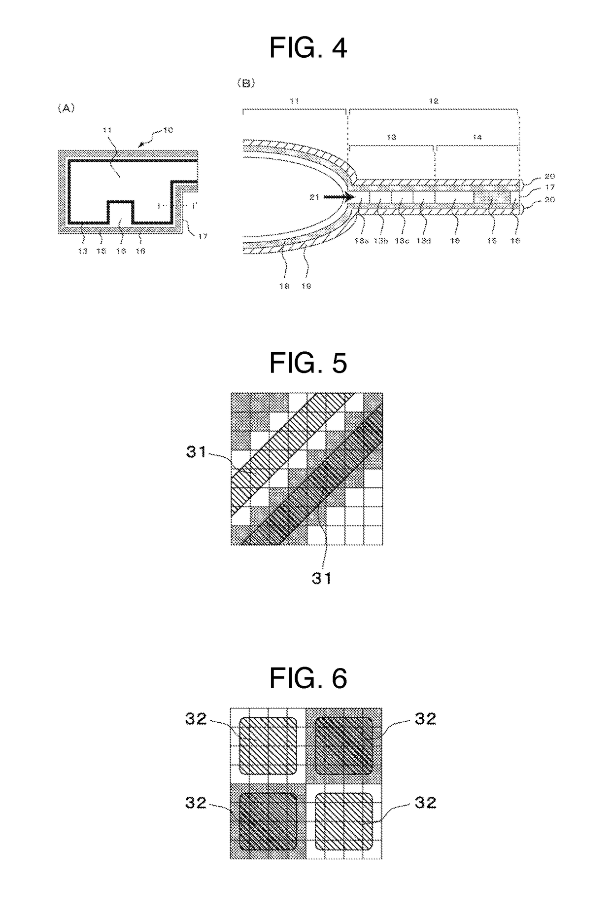
[0107]The hollow weave airbag provided with the twill-like structure area of the present invention in the outer edge part spaced apart from the outer peripheral joining part was lightweight, thin, and extremely excellent in the internal pressure maintainability.

example 3

[0108]The weave for an outer peripheral joining part was made of a 2 / 2 basket weave (FIG. 13-A) (13a), a reversible figured double weave (FIG. 13-B) (13b), and a 3 / 3 basket weave (FIG. 13-C) (13c) in this order from the inflation part side, and hollow weave base fabric was prepared in accordance with the manner of Example 1 except that the weaving was performed by providing an 8-harness twill weave (FIG. 9-C) or pointed twill weave (FIG. 9-I) (15) with a width of 12 mm in an outer edge part connected to the outer peripheral joining part such that the weave structure line extends along the outer peripheral shape of the inflation part.

[0109]The evaluation results are shown in TABLE 1.

[0110]The hollow weave airbag provided with the twill-like structure area of the present invention in the outer edge part connected to the outer peripheral joining part was lightweight, thin, and extremely excellent in the internal pressure maintainability.


PUM

PropertyMeasurementUnit
widthaaaaaaaaaa
melting pointaaaaaaaaaa

Abstract

The purpose of the present invention is to provide a hollow weave airbag wherein gas leakage from cut surfaces of a hollow weave airbag formed by lamination can be suppressed and internal pressure retention can be improved. Provided is a hollow weave airbag that is formed in an expandable bag shape by weaving at least two pieces of fabric, wherein: the hollow weave airbag includes an outer peripheral joining part positioned on the outer periphery of an expanding part, and an outer edge part extending to the outside of the outer peripheral joining part; at least part of the outer peripheral joining part and / or the outer edge part is provided with a twill-like structure area formed from a single weave structure; the twill-like structure area is configured such that when a continuous connection line is formed by tying peak crossover points or valley crossover points in any of the up, down, left, and right directions in a minimum unit mapping for weave structure mapping, the connection line can extend diagonally in the weave structure mapping when viewed as a whole; and the outer surface of the hollow weave airbag is formed by lamination.

Description

TECHNICAL FIELD[0001]The present invention relates to an airbag for an automobile, which is formed in an inflatable bag shape by a hollow weave, in particular, prevents gas leakage from a cut face of a laminated hollow weave airbag, and improves internal pressure maintaining performance.BACKGROUND ART[0002]With respect to an airbag installed as a safety device for an automobile, in an airbag prepared by a hollow weave, two pieces of base fabric are joined by a weave to form an inflatable inflation part, and in order to provide airtightness, a coating material such as a silicone resin is applied onto the outer surface.[0003]However, in a case of trying to obtain favorable internal pressure maintaining performance by such a method, it is required to increase the applying amount of a silicone resin, the thickness and the weight are increased, and the storability may be deteriorated in some cases. In addition, it is known that in the outer peripheral joining part positioned on the outer...

Claims


Application Information

Patent Timeline
Patent Type & Authority Applications(United States)
IPC IPC(8): B60R21/235D03D1/02
CPCB60R21/235D03D1/02B60R2021/23547B60R21/2342D10B2505/124D03D11/02D03D13/004D10B2331/04
Inventor HARABAYASHI, TEPPEI
Owner SUMISHO AIRBAG SYST CO LTD
Why Eureka
Try Eureka