
Presentation control device and presentation control method

a technology of control device and control method, applied in the direction of vehicle position/course/altitude control, process and machine control, instruments, etc., can solve the problem of large change in information presentation, and achieve the effect of reducing the anxiety of the occupan

Active Publication Date: 2018-11-15
DENSO CORP
View PDF4 Cites 5 Cited by
  • Summary
  • Abstract
  • Description
  • Claims
  • Application Information

AI Technical Summary

Benefits of technology

The present disclosure provides a presentation control device and method that can reduce the anxiety of a vehicle occupant by controlling their behavior. The device can do this by presenting information about the behavior change in a way that is easy for the occupant to understand. This helps the occupant predict the magnitude of the behavior change in advance, making them less likely to feel anxiety or unease. Overall, the device can make the control process more effective and comfortable for the occupant.

Problems solved by technology

In addition, the information presentation exhibits a large change with a short time by the process of temporarily advancing the presentation of a behavior change.

Method used


Image

  • Presentation control device and presentation control method
  • Presentation control device and presentation control method
  • Presentation control device and presentation control method

Examples


first embodiment

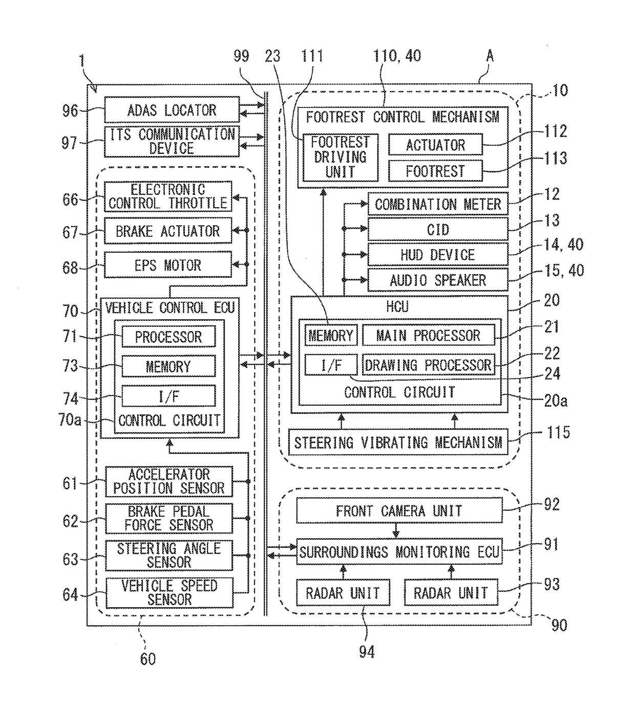
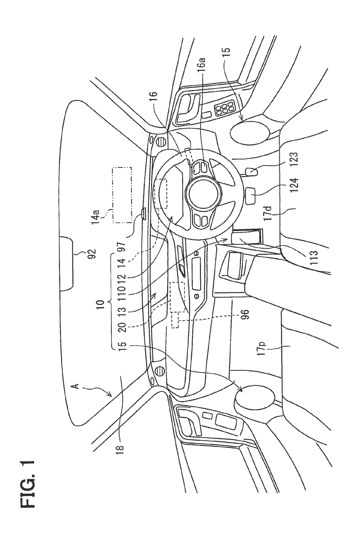
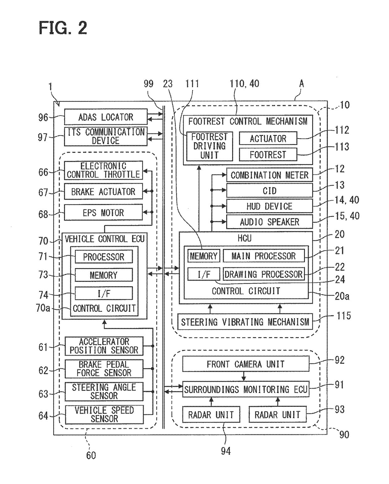
[0036]A human machine interface (HMI) control unit (HCU) 20 of a first embodiment is an electronic device mounted on an own vehicle A as illustrated in FIGS. 1 and 2. The HCU 20 is one of a plurality of nodes provided in an in-vehicle network 1 which is mounted on the own vehicle A. The in-vehicle network 1 includes an ADAS locator 96, an ITS communication device 97, an external recognition system 90, a vehicle control system 60, and an HMI system 10. These configurations are connected to a communication bus 99 and capable of exchanging information therebetween by communication.

[0037]The advanced driver assistance systems (ADAS) locator 96 is provided with a GNSS receiver, an inertial sensor such as a gyroscopic sensor, and a memory which stores map data. The global navigation satellite system (GNSS) receiver receives positioning signals from a plurality of artificial satellites. The ADAS locator 96 measures the position of the own vehicle A by combining positioning signals received...

second embodiment

[0118]A control status image 250 of a second embodiment illustrated in FIGS. 13 to 16 is a modification of the first embodiment. The control status image 250 includes a flying object image portion 252 as a display element corresponding to the arrow image portion 52 (refer to FIG. 8) of the first embodiment. The flying object image portion 252 is displayed in a slightly floating mode from a virtual road surface on display represented by lane marking image portions 51a to 51c. The flying object image portion 252 includes a pair of triangular figures which are symmetrically disposed right and left. Hereinbelow, the details of the control status image 250 displayed in each scene will be described in order with reference to FIGS. 1, 3, and 4.

[0119]FIG. 13 illustrates a scene in which the own vehicle A passes the preceding vehicle A1 similarly to FIG. 6. In the scene, the behavior change determination section 33 determines that the target movement amount TM in the lateral direction is lar...


PUM


Abstract

A presentation control device controlling an information presentation device in a vehicle equipped with a vehicle control device for controlling an acceleration-deceleration function or a steering function, includes: a plan acquisition section that acquires a travel plan indicating a control content of the vehicle; a behavior change determination section that determines whether a control target value relating to a magnitude of a behavior change included in the travel plan is larger than an advance threshold; and a presentation execution section that presents the control content to the occupant using the information presentation device in accordance with the behavior change occurring in the vehicle when the control target value is smaller than the advance threshold, and presents the control content temporarily in advance of an actual behavior change when the control target value is larger than the advance threshold.

Description

CROSS REFERENCE TO RELATED APPLICATION[0001]This application is based on Japanese Patent Application No. 2015-219722 filed on Nov. 9, 2015, the disclosure of which is incorporated herein by reference.TECHNICAL FIELD[0002]The present disclosure relates to a presentation control device that is mounted on a vehicle and controls an information presentation device that presents information to an occupant of the vehicle and a presentation control method.BACKGROUND ART[0003]As a conventional technique, for example, Patent Literature 1 discloses a system that collectively presents pieces of information required for a lane change to a driver who is driving a vehicle to support the driving of the driver. Specifically, in the system disclosed in Patent Literature 1, information such as the direction of the lane change, the permissibility of the lane change, a waiting time for the lane change, an acceleration or deceleration required for the lane change, and the position of another vehicle is p...

Claims


Application Information

Patent Timeline
Patent Type & Authority Applications(United States)
IPC IPC(8): B60W50/08B60K35/00B60W50/14B60W50/16
CPCB60W50/085B60K35/00B60W50/14B60W50/16B60W2050/146G05D1/021G05D2201/0213B60W30/18163G08G1/167B60K35/22B60K35/28B60K2360/175
Inventor FUJISAWA, YUKIKAMIYA, AKIRA
Owner DENSO CORP
Learn More