
Variable compression ratio engine

Active Publication Date: 2018-11-15
MCE 5 DEV
View PDF3 Cites 3 Cited by
  • Summary
  • Abstract
  • Description
  • Claims
  • Application Information

AI Technical Summary

Benefits of technology

The present disclosure is about a variable compression ratio engine that can adjust the position of the top dead center of the combustion piston to optimize engine performance. The engine includes a self-contained device for adjusting the position of the piston, which has high- and low-pressure hydraulic chambers, a calibrated conduit, and mechanical return means to bring the device back to a normal position. The characteristics of the mechanical return means and the calibrated conduit are equally configured to enable the length adjustment of the rod in response to average traction and compression efforts. The high- and low-pressure hydraulic chambers are defined by the spaces created on either part of the piston as it moves in the cylinder. The self-contained adjustment device is located in a least one of the movable members and can adjust the position of the engine compression ratio command member or the length of the connecting rod. The compression ratio engine has a mechanism for determining the compression ratio and includes at least two calibrated compression conduits. The conduit is configured to enable turbulent flow and the return means include a spring.

Problems solved by technology

The displacement variation must be of a high amplitude for it to have any significant effect on fuel efficiency, and this is technologically challenging to implement.
However, the combustion forces partly absorbed in the hydraulic chamber of the rod are not returned, which makes the solution particularly inefficient.
This solution does not therefore enable adjustments in the compression ratio depending on the load applied during one or series of engine cycles.
The solution proposed in U.S. Pat. No. 4,111,164 further leads to intensely solicit the mechanical components of the connecting rod (spring, hydraulic chamber) during operation of the engine, which accelerates their wear out and reduces the reliability of the system.
Furthermore, the hydraulic chamber of the solution presented in U.S. Pat. No. 4,111,164 is particularly sensitive to temperature changes in the hydraulic fluid, and this, in combination with the sensitivity to the engine speed, makes it very difficult to predict the behavior of the rod.
The external command systems are generally complex and lead to energy losses, in addition to being unreliable.
Furthermore, compression ratio control is not continuous and the accessible value range is often too limited.

Method used


Image

  • Variable compression ratio engine
  • Variable compression ratio engine
  • Variable compression ratio engine

Examples


example 1

Self-Contained Device Built into the Rod of a Conventional Engine

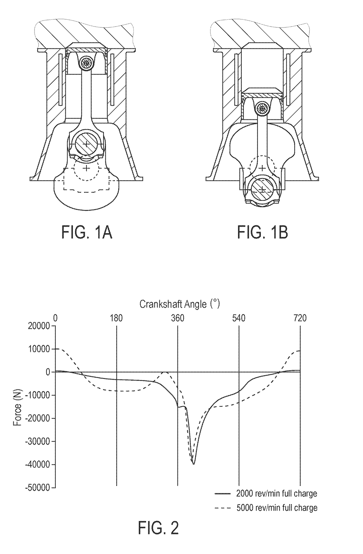
[0142]According to the first embodiment, the self-contained device is built into the rod of a conventional engine as shown in FIGS. 1A and 1B, with the following characteristics:[0143]Combustion piston diameter: 75 mm;[0144]Stroke 84 mm;[0145]Three-cylinder forming 1113 cm̂3 of capacity;[0146]Maximum load: 25 bars MEP (mean effective pressure) for a maximum combustion pressure of 130b;

[0147]A rod corresponding to this first example is shown in FIG. 9.

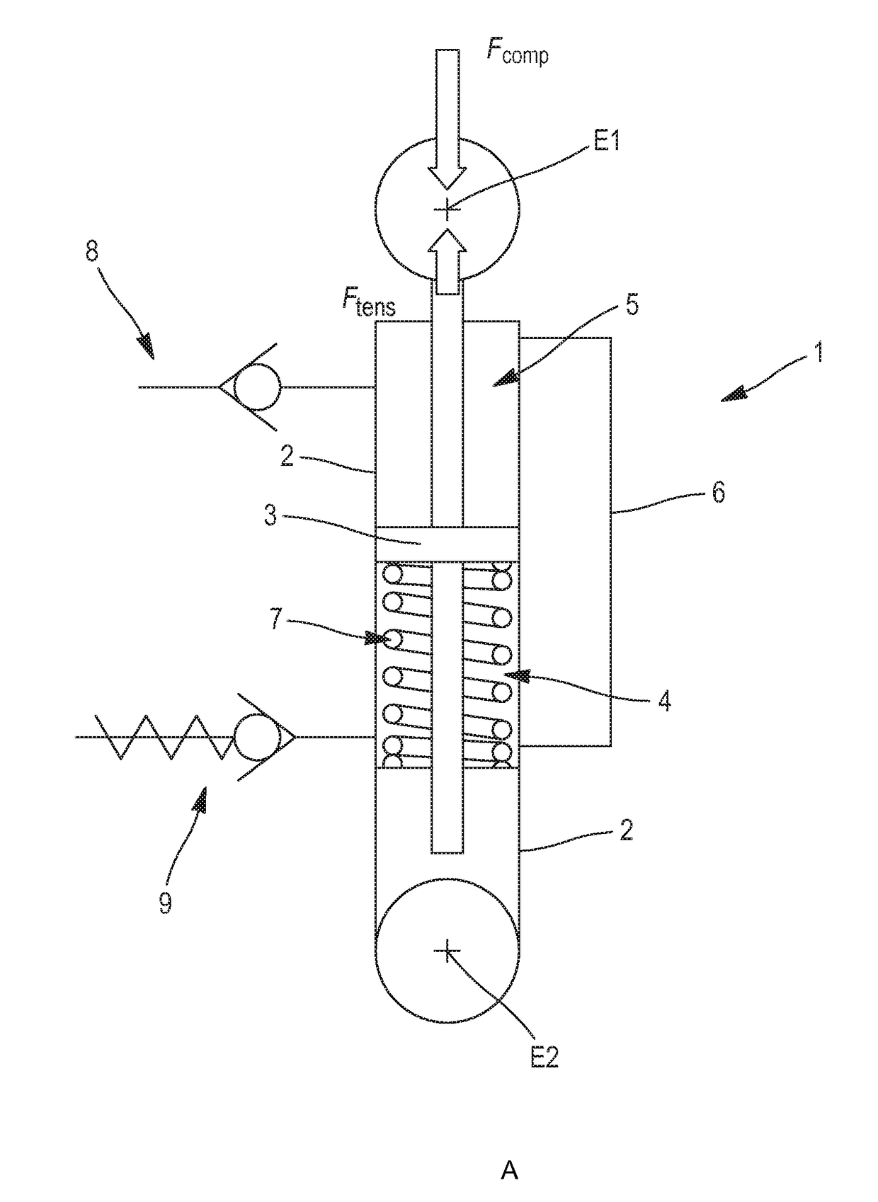
[0148]In this example, the big end of the rod is shaped to form the cylinder 2 in which the piston 3, which is attached to the rod, through the stem 9, runs. The opening of the cylinder 2 is closed by the cover 13, which can be screwed to the cylinder 2. The piston 3 thus defines in the cylinder 2 the high-pressure chamber 4 and the low-pressure chamber 5. The center-to-center spacing of the rod is 150 mm, when it is in its nominal position, and 146 mm when compressed and...

example 2a

Self-Contained Device Built Into a Control Member of the Variable Compression Ratio Engine

[0156]FIG. 11 shows an overall diagrammatic section of a variable compression ratio engine. From EP1407125 certain mobile members that constitute such an engine are known:[0157]a combustion engine, able to play in a cylinder of the engine and attached to a transmission organ;[0158]a roller that moves along the engine crankcase, which guides the translation movement of the transmission member.[0159]a sprocket wheel that interacting with the first rack and pinion of the transmission member and ensure transmission of movement between the combustion piston and the engine crankshaft; and[0160]a connecting rod interacting, at the first end, with the sprocket wheel and in the second end with the crankshaft.

[0161]A control element, that equally cooperates with the wheel, enables change of the vertical position of the wheel in the engine, and adjustment of the top dead center of the piston stroke in the...

example 2b

Self-Contained Device Built Into a Command Member of the Variable Compression Ratio Engine

[0170]FIG. 12 shows a diagram of an overall section of a variable compression ratio engine. Components of such an engine are known from Document DE102010019756. They include the following in the crankcase:[0171]a combustion piston, capable of in the cylinder and attached to the connecting rod;[0172]a transmission structure attached to the rod and ensuring transmission of movement between the combustion piston and one crankshaft of the engine; and[0173]A command structure interacting with the transmission organ as well and enabling adjustment of the top dead center of the piston stroke in the cylinder. Thus is an engine created with the possibility of varying its compression ratio.

[0174]In this type of engine, combustion efforts apply to the combustion piston and traction forces transmitted by the crankshaft are both transmitted through the transmission member to the command member.

[0175]The eng...


PUM


Abstract

A variable compression ratio engine comprises a stationary engine block in which movable members interact to enable a piston to translate in a combustion cylinder of the engine block, defining a stroke of the combustion piston The engine further comprises a self-contained device for adjusting the position of the top dead center of the combustion piston, the self-contained device being connected to or built into at least one of the movable members and having a high-pressure hydraulic chamber to counteract the combustion and inertial forces at the bottom dead center, a low-pressure hydraulic chamber to counteract the inertial forces at the top dead center, at least one calibrated conduit to enable hydraulic fluid to flow between the high- and low-pressure hydraulic chambers, and return means to bring the device back to a nominal position.

Description

CROSS-REFERENCE TO RELATED APPLICATIONS[0001]This application is a national phase entry under 35 U.S.C. § 371 of International Patent Application PCT / FR2016 / 052985, filed Nov. 17, 2016, designating the United States of America and published as International Patent Publication WO 2017 / 085410 A1 on May 26, 2017, which claims the benefit under Article 8 of the Patent Cooperation Treaty to French Patent Application Serial No. 1561059, filed Nov. 17, 2015.TECHNICAL FIELD[0002]The application relates to an engine and the elements of a variable compression ratio engine.BACKGROUND[0003]As a foreword, it should be recalled that a connecting rod of an internal combustion engine is associated on the side of its foot with the bearing of a combustion piston and on the side of its head with the bearing of a crankshaft. These two bearings generally have parallel axes. As shown, respectively, in FIGS. 1A and 1B, the function of the rod is to transmit the translation movement of the piston from a “t...

Claims


Application Information

Patent Timeline
IPC IPC(8): F02B75/04F16C3/28F16C7/06F02D15/02
CPCF02B75/045F16C3/28F02B75/048F16C7/06F02D15/02F02B75/04F16C7/04
Inventor DURY, PHILIPPEMIEHE, YVES
Owner MCE 5 DEV
Features
  • Generate Ideas
  • Intellectual Property
  • Life Sciences
  • Materials
  • Tech Scout
  • Unparalleled Data Quality
  • Higher Quality Content
  • 60% Fewer Hallucinations
Learn More