
Skin material for vehicle interior

a technology for interiors and skins, applied in the direction of fibre light guides, lighting and heating apparatus, instruments, etc., can solve the problems of insufficient inability to reduce inability to reduce diameter or cut multifilaments with small fineness, etc., to achieve sufficient suppression of abrasion and scratch of side emission type optical fibers during cutting, and the effect of sufficien

Active Publication Date: 2018-11-29
TOYOTA BOSHOKU KK +1
View PDF0 Cites 0 Cited by
  • Summary
  • Abstract
  • Description
  • Claims
  • Application Information

AI Technical Summary

Benefits of technology

The patent is about a special textile material that uses optical fibers to produce light for automobile interiors. The text describes a way to control the textile's texture and brightness to reduce uneven light emission. It also mentions that the optical fibers are protected from damage and excessive appearance on surface parts. The text suggests that using optical fibers in the material should have finer fibers than ordinary yarns, and the combination of optical fibers and yarns should be carefully considered to achieve the desired appearance and performance. The text also mentions that some manufacturers often use multifilaments made of synthetic resin fibers as a skin material for vehicle interiors, and optical fibers can be woven into these materials to provide a lighting effect.

Problems solved by technology

However, in this embodiment, the side emission type optical fibers appear in a large amount on the outermost surface of the skin material, which is disadvantageous to abrasion and scratch.
However, in this case, abrasion may cause multifilaments having small fineness to be reduced in diameter or cut.
Furthermore, when multifilaments having insufficiently large fineness are used and the multifilaments are worn, the side emission type optical fibers appear on the outermost surface of the skin material, which may insufficiently suppress the abrasion and scratch of the side emission type optical fibers.
On the other hand, when multifilaments having excessively large fineness are used, the appearance as the skin material changes.
As a result, the optical fibers cannot be sufficiently fixed, which may cause the optical fibers to be frayed during cutting.

Method used


Image

  • Skin material for vehicle interior
  • Skin material for vehicle interior
  • Skin material for vehicle interior

Examples


Embodiment Construction

[0036]Hereinafter, the present invention will be described in detail with reference to the drawings.

[0037]The particulars shown herein are by way of example and for purposes of illustrative discussion of embodiments of the present invention only, and are presented in the cause of providing what is believed to be the most useful and readily understood description of the principles and conceptual aspects of the present invention. In this regard, no attempt is made to show structural details of the present invention in more detail than is necessary for the fundamental understanding of the present invention, and the description is taken with the drawings, making apparent to those skilled in the art how some forms of the present invention may be embodied in practice.

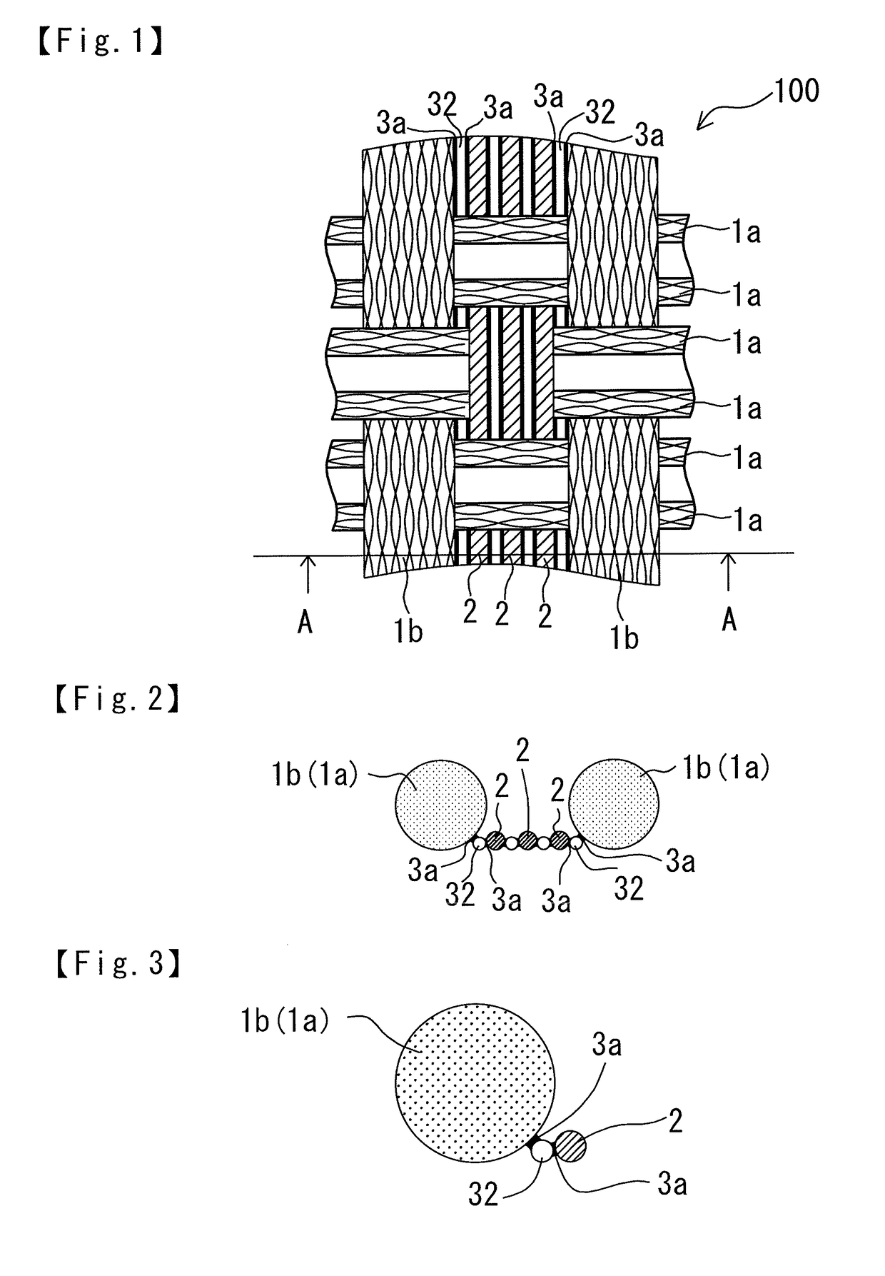
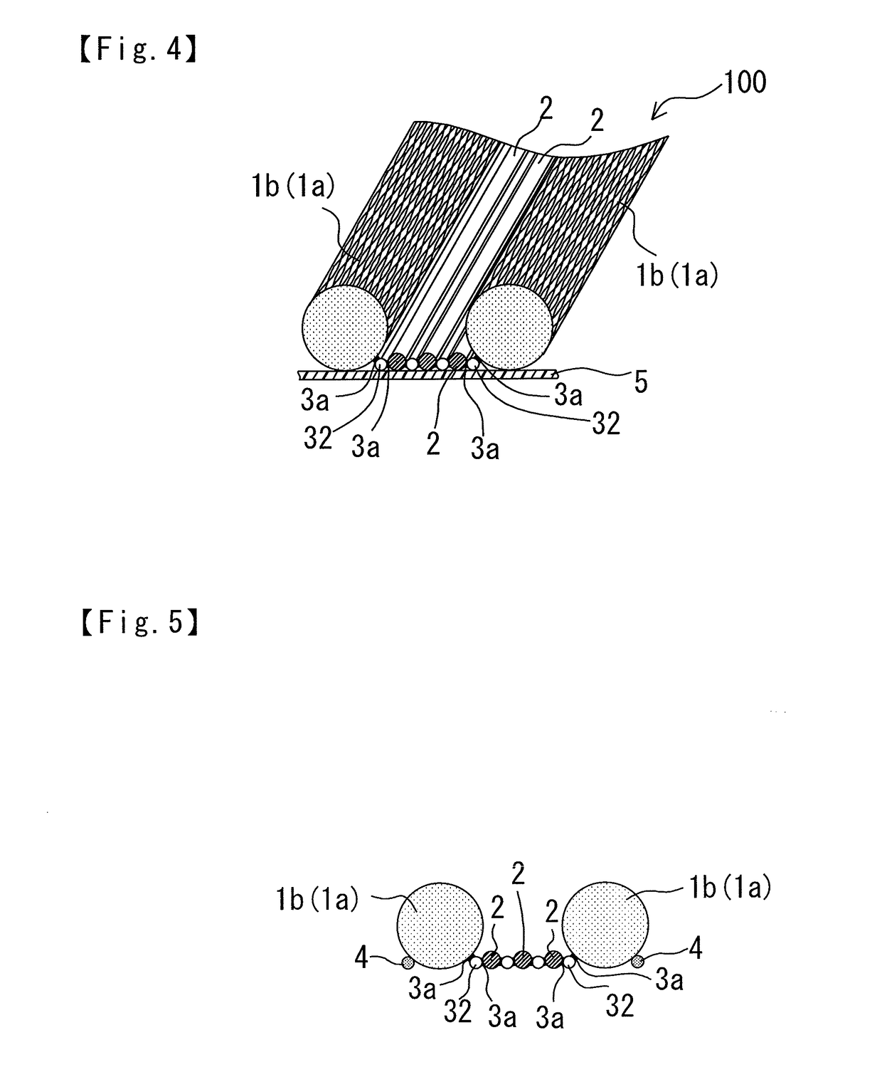
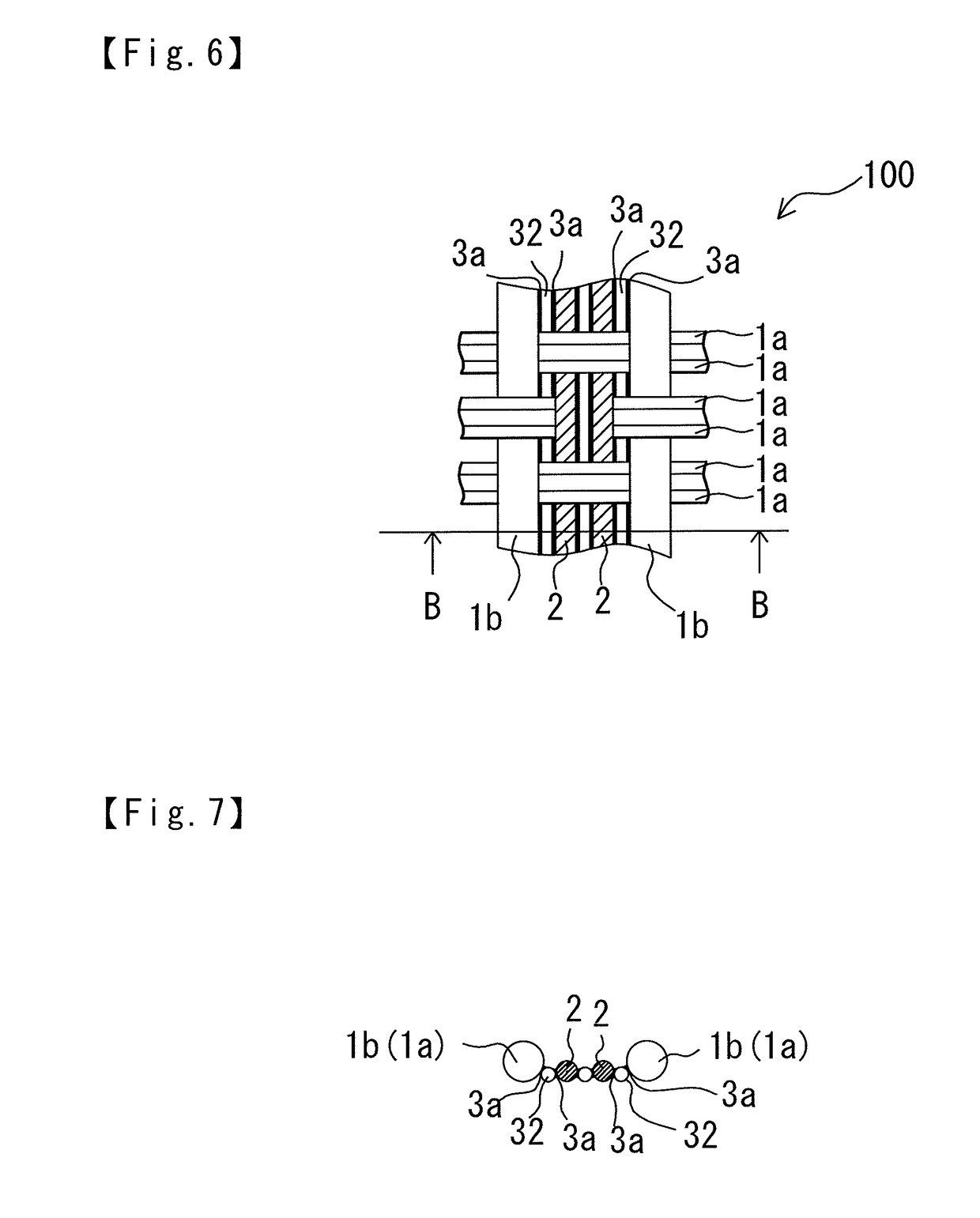
[0038]A skin material for vehicle interior 100 of the present invention is bonded to a resinous vehicle interior base 5 (see FIGS. 4 and 8). The skin material for vehicle interior 100 includes a woven fabric 10 woven by using...


PUM

PropertyMeasurementUnit
diameteraaaaaaaaaa
temperatureaaaaaaaaaa

Abstract

The skin material includes a woven fabric woven by using synthetic resin fibers 1b and 1a, side emission type optical fibers, and heat fusible fibers as warps or wefts. A ratio (dS / df) of fineness (dS) of the synthetic resin fibers to fineness (df) of the side emission type optical fibers is from 1.5 to 7.0. The synthetic resin fibers and the side emission type optical fibers adjacent to the synthetic resin fibers are bonded in respective longitudinal directions thereof by the heat fusible fibers. When a plurality of the side emission type optical fibers are woven between the adjacent synthetic resin fibers, the adjacent side emission type optical fibers are bonded to each other in the longitudinal direction by the heat fusible fibers.

Description

CROSS-REFERENCE TO RELATED APPLICATIONS[0001]The present application claims priority under 35 U.S.C. § 119 of Japanese Application No. 2017-104694 filed on May 26, 2017, the disclosure of which is expressly incorporated by reference herein in its entirety.BACKGROUND1. Technical Field[0002]The present invention relates to a skin material for vehicle interior. The skin material for vehicle interior is woven by using synthetic resin fibers, side emission type optical fibers, and heat fusible fibers, forms a vehicle interior design surface, functions as lighting, and suppresses the fray of the side emission type optical fibers in an end edge part cut into a predetermined shape and size, wherein the synthetic resin fibers and the side emission type optical fibers adjacent to each other are bonded in longitudinal directions thereof.2. Related Art[0003]The use of optical fibers is expanding in technical fields of optical communication and the like along with popularization of the Internet ...

Claims


Application Information

Patent Timeline
Patent Type & Authority Applications(United States)
IPC IPC(8): B60Q3/54B60R13/02D02G3/44D03D1/00F21V8/00
CPCB60Q3/54B60R13/02D02G3/441D03D1/0088G02B6/001B60Q2500/10B60R2013/0287D03D2700/0144D10B2331/02D10B2331/04D10B2401/20D10B2505/12F21V2200/15D03D15/00G02B6/0005D10B2401/041B60Q3/64D03D15/587D03D15/547D03D15/283
Inventor YAMADA, TAKAMASASAKAI, HIROHIKOYAMAMOTO, TAKAYOSHI
Owner TOYOTA BOSHOKU KK
Learn More