
Particle impregnating device

a technology of impregnating device and particle, which is applied in the direction of mechanical vibration separation, physical treatment, textile treatment carriers, etc., can solve the problems of increasing the size of the facility, and increasing the running cost of drying energy, so as to suppress the occurrence of differences in compression quantity and vibration propagation, and the effect of easy movemen

Active Publication Date: 2018-11-29
TOYOTA BOSHOKU KK
View PDF4 Cites 1 Cited by
  • Summary
  • Abstract
  • Description
  • Claims
  • Application Information

AI Technical Summary

Benefits of technology

The present invention provides a small and inexpensive particle impregnating device that can effectively impregnate particles into a nonwoven fabric. By propagating ultrasonic vibration to the fibers of the nonwoven fabric and particles, the particles on the surface of the nonwoven fabric are impregnated into the nonwoven fabric while the adhesion of the particles onto the vibrating member is suppressed. The compression quantity of the nonwoven fabric and the contact quantity of the vibrating member are adjusted to suppress the propagation of the vibration to the lower face side of the nonwoven fabric, thereby suppressing fall of the particles from the nonwoven fabric. This results in the effective impregnation of particles into the nonwoven fabric. The vibrating member is formed in a plate shape, reducing its weight and allowing effective propagation of the vibration to the nonwoven fabric. A conveyor including a placing body makes it easy to move the nonwoven fabric. A feeding roller rotatably and liftably above the placing body positively feeds out the nonwoven fabric, suppressing differences in compression quantity and vibration propagation due to delay in moving or slipping of the fabric. A lowered and rotationally driven feeding roller is effective in suppressing these differences. The device enables the uniform impregnation of particles into the nonwoven fabric, reducing the size of facilities and installation spaces, investment, and running cost for drying.

Problems solved by technology

However, the conventional wet impregnating method requires a step of drying a nonwoven fabric after impregnation of particles and has many disadvantages such as increases in sizes of facilities and manufacturing steps and a higher running cost of drying energy.
The conventional dry impregnating method requires many rollers (for example, 50 rollers), and thus involves problems of an increase in sizes of facilities, increases in investment and installation space due to such a size increase, and very difficult adjustment of a clearance between the rollers and the conveyor belt.

Method used


Image

  • Particle impregnating device
  • Particle impregnating device
  • Particle impregnating device

Examples


examples

[0044]Hereinafter, the present invention will be explained in detail by way of Examples with reference to the drawings. In this Example, a nonwoven fabric 2 cut into a predetermined shape (for example, a flat rectangular shape) is indicated as an example of the “nonwoven fabric” according to the present invention (see FIG. 1).

(1) Construction of Particle Impregnating Device

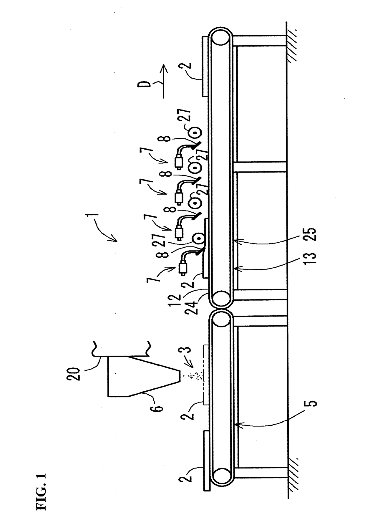
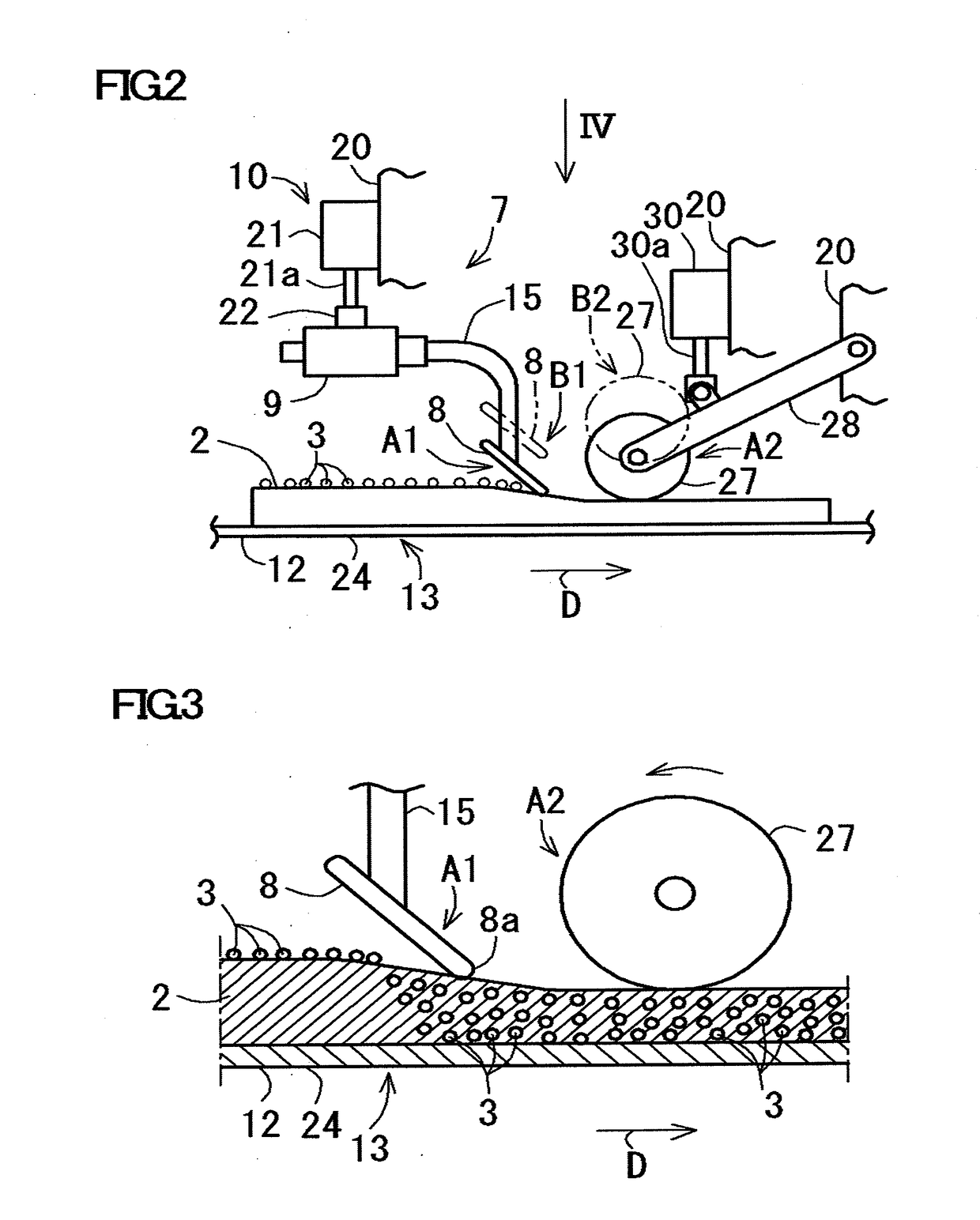
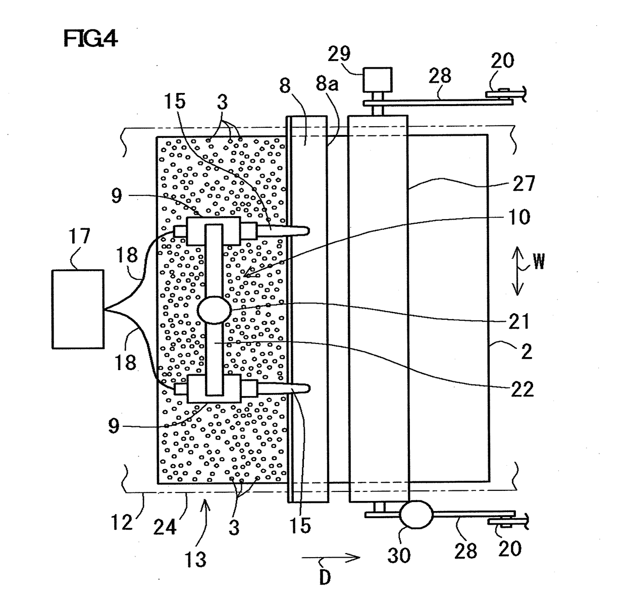
[0045]A particle impregnating device 1 according to this Example includes a belt conveyor 5 for conveying the nonwoven fabric 2 and a well-known particle spraying machine 6 arranged above the belt conveyor 5, as shown in FIG. 1. This particle impregnating device 1 includes a plurality of (four in the figure) vibrating devices 7 arranged along a conveying direction D in which the nonwoven fabric 2 is conveyed. Each of these vibrating devices 7 includes a vibrating member 8, a vibrator 9 and a lifting mechanism 10 as will be described below. Further, the particle impregnating device 1 includes a placing body 12 for ...


PUM

PropertyMeasurementUnit
Shapeaaaaaaaaaa

Abstract

The particle impregnating device includes a placing body for placing a nonwoven fabric having a surface on which particles are sprayed; a vibrating member which is provided above the placing body and extends in the width direction of the nonwoven fabric placed on the placing body; a vibrator which applies ultrasonic vibration to the vibrating member; a lifting mechanism which lifts up and down the vibrating member; and a moving mechanism which relatively moves the nonwoven fabric and the vibrating member in a surface direction orthogonal to the width direction of the nonwoven fabric. When the nonwoven fabric and the vibrating member are relatively moved by the moving mechanism, the vibrating member is lowered by the lifting mechanism, so that the nonwoven fabric is pressed and compressed by the vibrating member and ultrasonic vibration is applied to the vibrating member by the vibrator.

Description

CROSS-REFERENCE TO RELATED APPLICATIONS[0001]The present application claims priority under 35 U.S.C. § 119 of Japanese Application No. 2017-105970 filed on May 29, 2017, the disclosure of which is expressly incorporated by reference herein in its entirety.BACKGROUND1. Technical Field[0002]The present invention relates to a particle impregnating device, more specifically to a particle impregnating device for impregnating particles sprayed on a surface of a nonwoven fabric into the nonwoven fabric.2. Related Art[0003]A wet impregnating method and a dry impregnating method for impregnating particles into a nonwoven fabric are commonly known as conventional particle impregnating methods. This wet impregnating method normally involves dispersing particles in a liquid and immersing a nonwoven fabric in the liquid, thereby impregnating the particles into the nonwoven fabric. The dry impregnating method normally involves applying particles onto a surface of a nonwoven fabric and pressing an...

Claims


Application Information

Patent Timeline
IPC IPC(8): D06M23/08D06M10/02D06M10/04
CPCD06M23/08D06M10/02D06M10/04D04H1/407D04H1/413D06B13/00D06B23/04D06B15/00Y10T156/1744B05C3/05B05C11/02B05C19/04B05C9/14B05C11/028B06B2201/72B06B3/00B05C11/023B29C66/7292B29C66/8122B05C11/08B05B17/0646B05D1/12B05D1/42
Inventor MAEHARA, KAZUONAKAJIMA, RYOTONOZUKA, HIROMASA
Owner TOYOTA BOSHOKU KK
Learn More