
Vehicle and control method for vehicle

Active Publication Date: 2018-11-29
TOYOTA JIDOSHA KK
View PDF7 Cites 2 Cited by
  • Summary
  • Abstract
  • Description
  • Claims
  • Application Information

AI Technical Summary

Benefits of technology

The present invention reduces the amount of unburned fuel released from an engine when it is stopped or started. This is achieved by increasing the amount of oxygen flowing into the engine's catalyst when the engine is stopped, which leads to an increase in the amount of unburned fuel oxidized by the catalyst. This results in a reduction of the amount of unburned fuel released through the catalyst when the engine is stopped. Additionally, when the engine is started afterward, the catalyst has a large amount of stored oxygen, which enables it to sufficiently oxidize the unburned fuel adhering to the walls of the intake port and combustion chamber. Ultimately, this leads to a reduction of the amount of unburned fuel released from the engine through the catalyst when it is started.

Problems solved by technology

However, since the engine temperature may be relatively low at the time of this treatment, combustion of the unburned fuel in the combustion chamber may become unstable.
As a result, a large amount of unburned fuel may be released all at once from the internal combustion engine to the outside through the exhaust passage.
As a result, when the engine operation is started afterward, the catalyst has a large amount of oxygen stored therein.

Method used


Image

  • Vehicle and control method for vehicle
  • Vehicle and control method for vehicle
  • Vehicle and control method for vehicle

Examples


Embodiment Construction

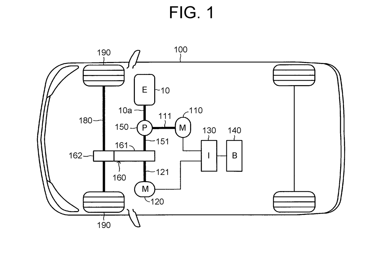
[0025]Hereinafter, a control device (which is hereinafter referred to as “implementation device”) for a vehicle drive system according to an embodiment of the present disclosure will be described with reference to the drawings. The implementation device is applied to a vehicle drive system mounted on a hybrid vehicle 100 illustrated in FIG. 1.

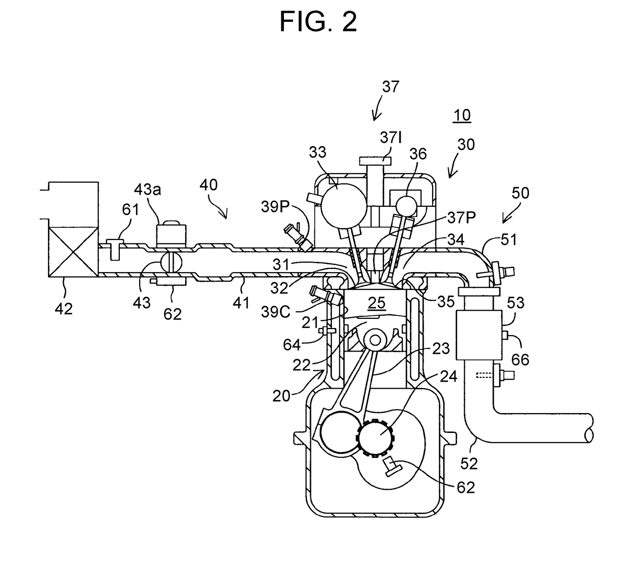
[0026]The vehicle drive system includes an internal combustion engine 10, a first motor-generator 110, a second motor-generator 120, an inverter 130, a battery (storage battery) 140, a motive power distribution mechanism 150, and a motive power transmission mechanism 160.

[0027]The motive power distribution mechanism 150 distributes torque (which is hereinafter referred to as “engine torque”) output from the internal combustion engine 10 (which is hereinafter simply referred to as “engine 10”) into “torque that rotates an output shaft 151 of the motive power distribution mechanism 150” and “torque that drives the first motor-generator 110 (which...


PUM


Abstract

A vehicle includes an internal combustion engine including an exhaust passage, a catalyst provided in the exhaust passage, and an electronic control unit. When the engine stop condition is established, the electronic control unit stops fuel injection and increases a catalyst inflow oxygen amount that is an amount of oxygen flowing into the catalyst by a specified oxygen increase amount. The engine stop condition is a condition for stopping operation of the internal combustion engine. The specified oxygen increase amount is larger than an increased part of the catalyst inflow oxygen amount that is increased by the stop of the fuel injection.

Description

INCORPORATION BY REFERENCE[0001]The disclosure of Japanese Patent Application No. 2017-101375 filed on May 23, 2017 including the specification, drawings and abstract is incorporated herein by reference in its entirety.BACKGROUND1. Technical Field[0002]The present disclosure relates to a vehicle that generates driving force for driving the vehicle and a control method for the vehicle.2. Description of Related Art[0003]When fuel injection is stopped in order to stop operation of an internal combustion engine (which is hereinafter referred to as “engine operation”), unburned fuel may adhere to the wall surface of an intake port and the wall surface of a combustion chamber. The unburned fuel may be released to the outside through an exhaust passage when the engine operation is stopped or while the engine operation is at a stopped state. Or the unburned fuel may be released, without being burned, to the outside through the exhaust passage when the engine operation is started after the e...

Claims


Application Information

Patent Timeline
IPC IPC(8): F02D41/02F02D41/04F01N3/10B60L50/16
CPCF02D41/0235F02D41/042F01N3/101B60W20/00F02D41/0002F02D41/1445F02D41/1454F02D41/1486F02D2041/0022F01N9/00F01N2430/00F01N2560/06F01N2590/11F02D41/0295F02N11/0814F02D2200/021B60K6/445B60W20/16B60W2710/0605B60W20/40B60W2710/0622B60W2710/0633B60W10/06B60W10/08Y02A50/20Y02T10/12Y02T10/40Y02T10/62F01N3/0864F02D9/08B60W2530/12
Inventor MIWA, KOJIKITAURA, KOICHITSUKAGOSHI, TAKAHIROINOSHITA, KENJISUZUKI, KAZUYAYOSHIDA, TAKERUCHINZEI, ISAOOTSUKA, KAORU
Owner TOYOTA JIDOSHA KK
Learn More