Gas turbine combustor and gaseous fuel supply method for gas turbine combustor

Active Publication Date: 2009-09-10
MITSUBISHI POWER LTD
View PDF22 Cites 22 Cited by
  • Summary
  • Abstract
  • Description
  • Claims
  • Application Information

AI Technical Summary

Benefits of technology

[0009]In accordance with the aspect of the present invention, use of the two types

Problems solved by technology

In JP-A-2006-161603, if there is a single fuel supply system between the three-way fuel transfer valve and the burner, supplying a fuel nozzle based on the LNG with the low Btu gas results in an increased fuel flow rate, which results in an increased pressure loss of the fuel nozzle.
This calls for changes in specifications of the gas compressor pressure, the control valve or other parts, or gaseous

Method used


Image

  • Gas turbine combustor and gaseous fuel supply method for gas turbine combustor
  • Gas turbine combustor and gaseous fuel supply method for gas turbine combustor
  • Gas turbine combustor and gaseous fuel supply method for gas turbine combustor

Examples


Example

First Embodiment

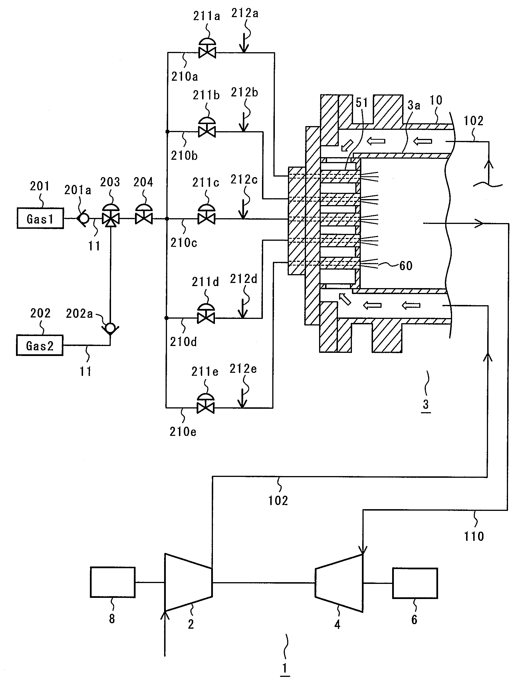
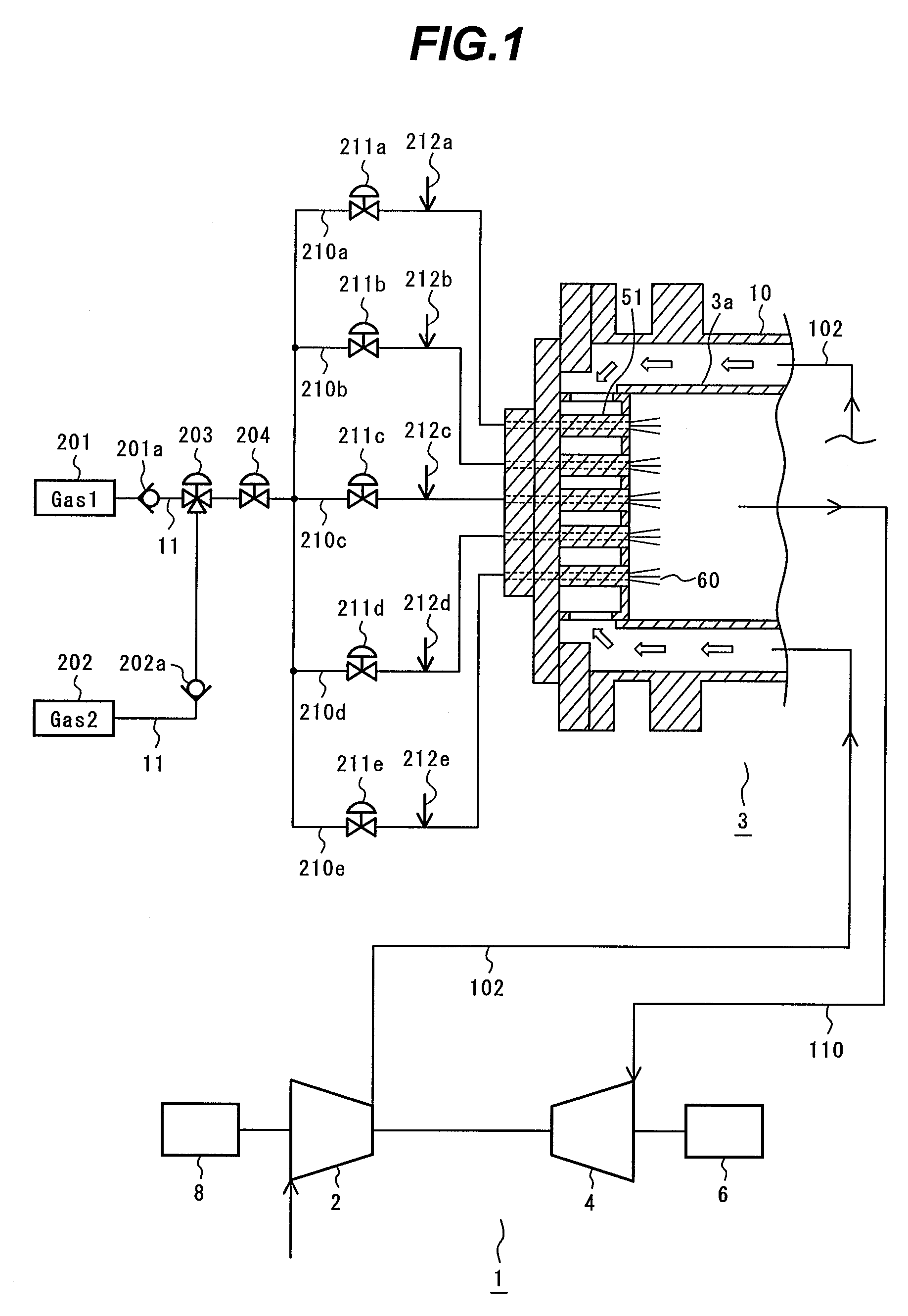
[0020]FIG. 1 is a schematic system diagram of a gas turbine power plant according to a first embodiment of the present invention. A gas turbine 1 typically includes an air compressor 2, a combustor 3, a turbine 4, a generator 6, and a start-up motor 8 for driving the gas turbine.

[0021]A plurality of burners 51 for injecting and mixing fuel and air and performing low NOx combustion is disposed at a head portion of the combustor 3. Combustion air 102 supplied to the combustor 3 is compressor discharge air compressed by the air compressor 2. The combustion air 102 flows through a space defined by a cylindrical liner 3a that forms a combustion chamber and an outer casing 10 that forms a pressure vessel. The combustion air 102 thereby cools a surface of the liner 3a and is distributed into cooling air for the liner 3a and combustion air for the burners 51.

[0022]The combustor 3 includes upstream parts of fuel supply system 11 supplying LNG 201 and off gas 202 which contain...

Example

Second Embodiment

[0032]FIG. 3 is a schematic system diagram of a gas turbine power plant according to a second embodiment of the present invention. In the second embodiment of the present invention, a gaseous fuel supply subsystem 210a and an off gas-exclusive subsystem 210f are employed to form a gaseous fuel supply subsystem for a pilot burner. The off gas-exclusive subsystem 210f is dedicated only to the off gas and leads to a burner 51a that is dedicated to the off gas and disposed in a combustor. The off gas-exclusive subsystem 210f includes a gaseous fuel flow control valve 211f and an on-off valve 211fa disposed therein. The on-off valve 211fa disposed upstream of the gaseous fuel flow control valve 211f prevents fuel leak. The gaseous fuel flow control valve 211f and the on-off valve 211fa are connected downstream to a gaseous fuel pressure regulation valve 204 to be shared therebetween. In addition, a purge subsystem 212f for supplying the fuel piping with purging nitrogen ...

Example

Third Embodiment

[0036]FIG. 5 is a schematic system diagram of a gas turbine power plant according to a third embodiment of the present invention. The third embodiment differs from the first embodiment in that a fuel subsystem leading to a pilot burner is formed by having a gaseous fuel supply subsystem 210a branching into two smaller subsystems. Specifically, the gaseous fuel supply subsystem 210a is branched into a first branch 410a and a second branch 310a at a point downstream thereof. The second branch 310a includes a gas shutoff valve 311a disposed therein. The gas shutoff valve 311a opens or closes according to the type of fuel and the gas turbine load. A pilot burner according to the third embodiment of the present invention has a larger gas hole area than the pilot burner in the second embodiment of the present invention. It is thereby assumed that the gas hole area of the fuel nozzle is adjusted such that the fuel pressure ratio of the fuel nozzle fall within the appropriat...


PUM


Abstract

A combustor includes two upstream parts of fuel supply system supplying gaseous fuels of two types having different heating values from each other, a three-way fuel transfer valve merging the two upstream parts of fuel supply system with each other, a plurality of gaseous fuel supply subsystems supplying a combustion chamber with the gaseous fuels supplied through the three-way fuel transfer valve and branched, and a plurality of burners injecting, corresponding to each of the gaseous fuel supply subsystems, the gaseous fuel supplied from the gaseous fuel supply subsystem into the combustion chamber.

Description

BACKGROUND OF THE INVENTION[0001]1. Field of the Invention[0002]The present invention relates to a gas turbine combustor and a gaseous fuel supply method for the gas turbine combustor.[0003]2. Description of Related Art[0004]JP-A-2006-161603 discloses a gas turbine apparatus having a compact structure capable of utilizing flammable gas at low cost by stably burning low Btu gas. JP-A-2006-161603 does not, however, disclose a relationship between a three-way fuel transfer valve that allows high Btu gas to merge with low Btu gas and a burner disposed downstream of the three-way fuel transfer valve.SUMMARY OF THE INVENTION[0005]To supply a combustor with the low Btu gas having a lower heating value than LNG, it is necessary to increase the fuel flow rate in proportion to reduction in the heating value.[0006]In JP-A-2006-161603, if there is a single fuel supply system between the three-way fuel transfer valve and the burner, supplying a fuel nozzle based on the LNG with the low Btu gas r...

Claims


Application Information

Patent Timeline
IPC IPC(8): F02C7/224
CPCF02C3/22F02C7/222F23R2900/00002F05D2220/75F23R3/36F02C7/232
Inventor KOIZUMI, HIROMIASAI, TOMOHIROINOUE, HIROSHINISHIJIMA, TSUNEMASAMURATA, HIDETARO
Owner MITSUBISHI POWER LTD
Why Eureka
Try Eureka