Heat recovery steam generator and power plant

a heat recovery steam generator and heat recovery technology, which is applied in steam generation using hot heat carriers, combustion types, and combustion using lumps and pulverulent fuels, etc., can solve the problems of incomplete combustion, increased concentration of harmful substances, and likely deficiency of oxygen in the other downstream auxiliary combustor of exhaust gas, etc., to achieve good combustion state, increase the flow rate of exhaust gas supplied to the heat recovery steam generator, and high concentration

Active Publication Date: 2016-08-16
KK TOSHIBA
View PDF15 Cites 0 Cited by
  • Summary
  • Abstract
  • Description
  • Claims
  • Application Information

AI Technical Summary

Benefits of technology

[0007]Further, when the output of a gas turbine increases, the flow rate of an exhaust gas supplied to the heat recovery steam generator increases. The amount of fuel fed to an auxiliary combustor(s), having a plurality of burners, may therefore be reduced. The reduction in the fuel feed is likely to cause unstable combustion in each burner, resulting in an extremely high concentration of a harmful gas, such as carbon monoxide, in the exhaust gas.
[0008]It is therefore an object of the present invention to solve the above problems in the prior art and provide a heat recovery steam generator and a power plant which can maintain a good combustion state in the burners of an auxiliary combustor and can reduce the emission of a harmful gas, such as carbon monoxide, from the auxiliary combustor.

Problems solved by technology

A heat recovery steam generator having a plurality of auxiliary combustors has the following problems: When the auxiliary combustors are operated simultaneously, a large proportion of oxygen contained in an exhaust gas is consumed in a first-stage auxiliary combustor disposed most upstream in the flow direction of the exhaust gas, whereby the exhaust gas is likely to be deficient in the amount of oxygen in the other downstream auxiliary combustor(s).
There is, therefore, a possibility of incomplete combustion and thus an increase in the concentrations of harmful substances, such as carbon monoxide, nitrogen oxide, etc. in the other auxiliary combustor(s).
The reduction in the fuel feed is likely to cause unstable combustion in each burner, resulting in an extremely high concentration of a harmful gas, such as carbon monoxide, in the exhaust gas.

Method used


Image

  • Heat recovery steam generator and power plant
  • Heat recovery steam generator and power plant
  • Heat recovery steam generator and power plant

Examples


Embodiment Construction

[0019]A preferred embodiment of a heat recovery steam generator according to the present invention will now be described with reference to the accompanying drawings.

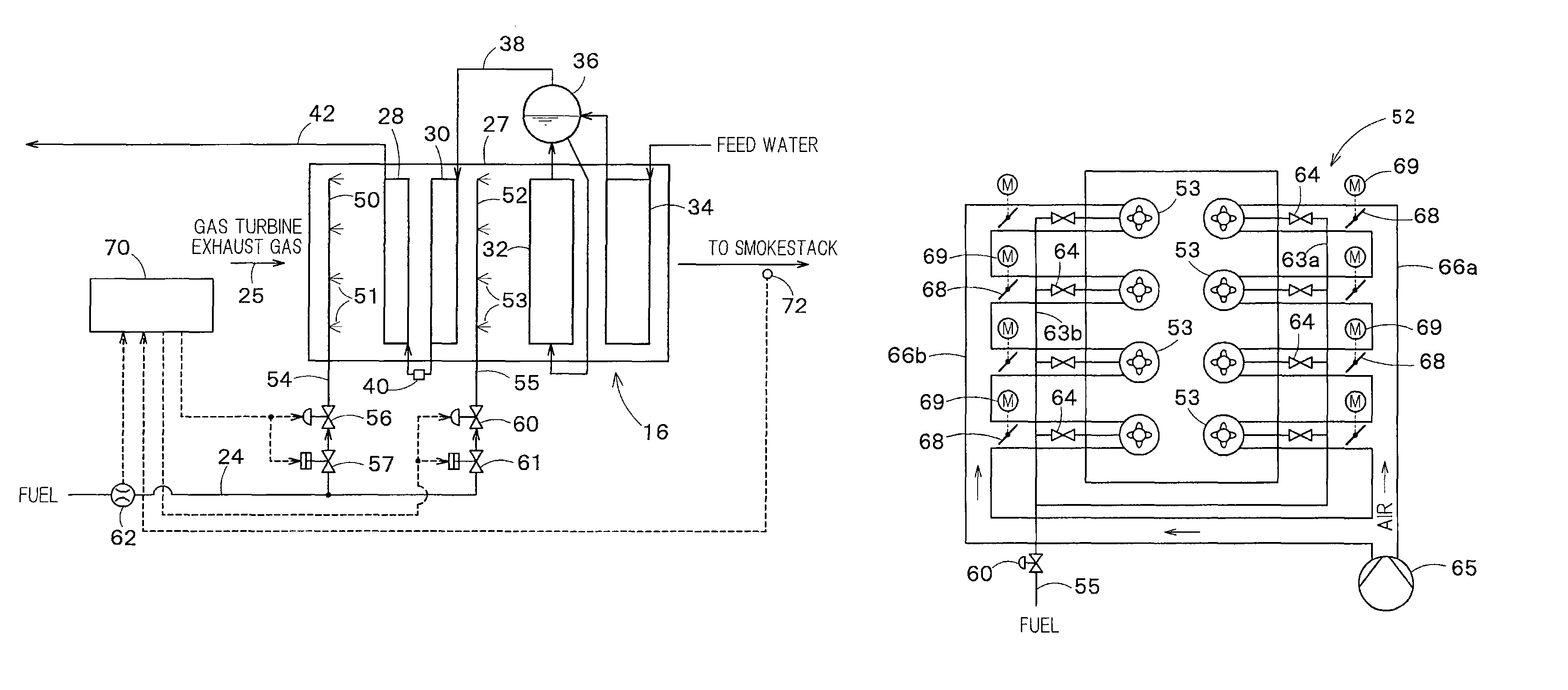
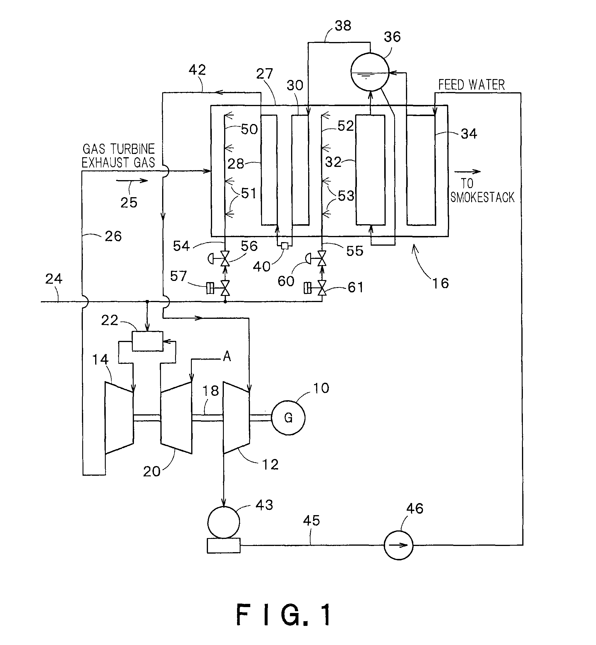
[0020]FIG. 1 is a system diagram of a combined cycle power plant in which the heat recovery steam generator of the present invention is applied.

[0021]In FIG. 1, reference numeral 10 represents a power generator, 12 represents a steam turbine, and 14 represents a gas turbine. Reference numeral 16 represents a heat recovery steam generator.

[0022]The power generator 10 is coupled to the steam turbine 12 and the gas turbine 14 by the same drive shaft 18. Further, an air compressor 20 is coupled to the drive shaft 18. The air compressor 20 compresses air A, which has been taken in from the outside, into a high-temperature and high-pressure state and supplies the compressed air to a combustor 22. In the combustor 22, a fuel that has been supplied from a fuel system 24 is mixed with compressed air and burns, and the high-temper...


PUM


Abstract

A heat recovery steam generator has a plurality of heat exchangers, including superheaters 28, 30, an evaporator 32 and an economizer 34, disposed in a duct 27 along the flow direction of an exhaust gas 25 from a gas turbine 14, and generates steam by utilizing the exhaust gas 25 from the gas turbine 14. The heat recovery steam generator includes: auxiliary combustors 50, 52, each disposed upstream of one of the heat exchangers, for heating the exhaust gas by means of burners; and an air supply device for supplying air to the burners of the auxiliary combustor 52 from the outside of the duct.

Description

CROSS-REFERENCE TO RELATED APPLICATION[0001]This application is a Continuation Application of PCT Application No. PCT / JP2012 / 064233, filed May 31, 2012 and based upon and claiming the benefit of priority from Japanese Patent Application No. 2011-122420, filed on May 31, 2011, the entire contents of which are incorporated herein by reference.TECHNICAL FIELD[0002]Embodiments of the present invention relate to a heat recovery steam generator having an auxiliary combustor and to a power plant.BACKGROUND ART[0003]From the viewpoint of enhancing thermal efficiency, combined cycle power generation is becoming mainstream in recent thermal power plants. A combined cycle power plant is a power plant comprising a combination of a gas turbine, a steam turbine and a heat recovery steam generator. A high-temperature and high-pressure combustion gas is fed from a combustor to the gas turbine so that the combustion gas, through its expansion, rotates the gas turbine, thereby rotating a power genera...

Claims


Application Information

Patent Timeline
Patent Type & Authority Patents(United States)
IPC IPC(8): F01K23/10F23N5/00F23C5/08
CPCF23N5/00F23C5/08F01K23/103F01K23/101F01K23/105F01K23/106Y02E20/14Y02E20/16Y02P80/15F22B1/18F22B35/00
Inventor NAKAMURA, KEIICHISHIMADA, HIDEAKI
Owner KK TOSHIBA
Why Eureka
Try Eureka