Apparatus and method for diagnosing electric power equipment using thermal imaging camera

a technology of thermal imaging and apparatus, applied in the direction of material flaw investigation, optical radiation measurement, instruments, etc., can solve the problems of increased leakage current, electrical abnormalities in electric power equipment, equipment malfunction, etc., to improve diagnosis accuracy, short time, and reduce diagnosis time

Active Publication Date: 2018-11-29
KOREA ELECTRIC POWER CORP
View PDF6 Cites 6 Cited by
  • Summary
  • Abstract
  • Description
  • Claims
  • Application Information

AI Technical Summary

Benefits of technology

The electric power equipment diagnosis apparatus and method using a thermal imaging camera described in this patent can automatically diagnose equipment as normal or abnormal, and can continue to diagnose while the vehicle is traveling. It can also improve accuracy of diagnosis through pattern analysis. The technology used is an algorithm that can automatically analyze a large amount of data from thermal images quickly and accurately, reducing human error and allowing for a faster analysis time. Overall, this apparatus and method can identify abnormal equipment and produce an analysis report automatically.

Problems solved by technology

With electric power equipment operated under high voltage, environmental, mechanical, thermal, and electrical deterioration is inevitable due to complex causes, thereby resulting in electrical abnormalities in the electric power equipment.
For example, such electrical abnormalities cause surface cracks, erosion tracking, increased leakage current, heat, ultrasonic sound, light, and mechanical vibrations in the equipment, and when this status continues, electric breakdown occurs, finally resulting in malfunctioning of the equipment.
However, this diagnosis method has a disadvantage of taking much time for diagnosis.
Further, although some power equipment is diagnosed by using a simple diagnosis device mounted on a vehicle, there is a problem that it takes much time to diagnose electric power equipment at every single place because storing a captured image is not performed during traveling of the vehicle but performed in a stationary state of the vehicle.
Therefore, there are many cases where deteriorated points cannot be identified due to differences in the level of analytical technique of the analysts, and the analysis time is long because the images are analyzed manually one by one.

Method used


Image

  • Apparatus and method for diagnosing electric power equipment using thermal imaging camera
  • Apparatus and method for diagnosing electric power equipment using thermal imaging camera
  • Apparatus and method for diagnosing electric power equipment using thermal imaging camera

Examples


Embodiment Construction

[0039]The present invention will be described in detail below with reference to the accompanying drawings. Repeated descriptions and descriptions of known functions and configurations which have been deemed to unnecessarily obscure the gist of the present invention will be omitted below. The embodiments of the present invention are intended to fully describe the present invention to a person having ordinary knowledge in the art to which the present invention pertains. Accordingly, the shapes, sizes, etc. of components in the drawings may be exaggerated to make the description clearer.

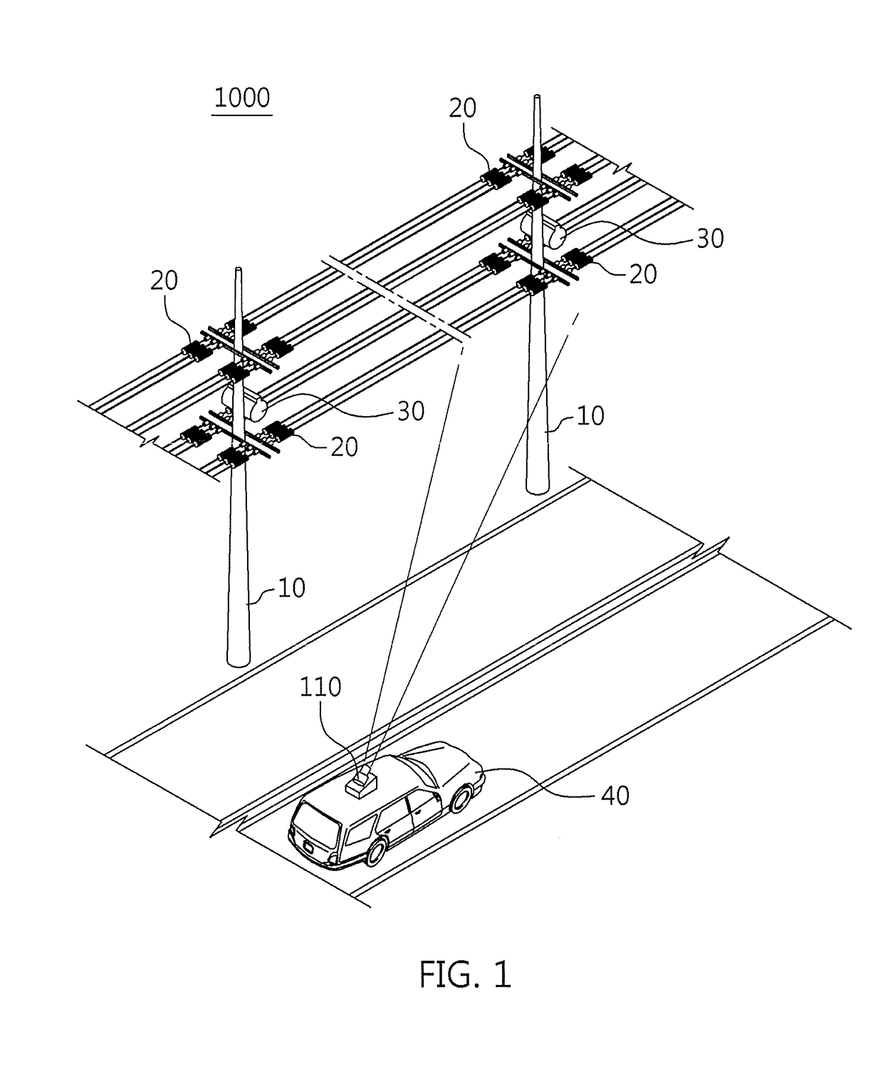
[0040]FIG. 1 is a conceptual diagram of an electric power equipment diagnosis system 1000 according to one embodiment of the present invention. The electric power equipment diagnosis system 1000 according to one embodiment of the present invention captures a thermal image of electric power equipment 20 using a measuring unit 110 mounted on a vehicle 40 and diagnoses operation status of electric power eq...


PUM


Abstract

Disclosed are an apparatus and method for diagnosing electric power equipment. The apparatus includes a measuring unit including a pan / tilt module mounted on the top of a vehicle and an imaging module mounted on an upper portion of the pan / tilt module, a determination unit for determining whether electric power equipment is detected by the measuring unit, a controller for performing control to capture a thermal image of the electric power equipment using the measuring unit, and a processing unit for dividing the thermal image into an analysis target equipment region, a non-interest equipment region, and a background noise region through pattern analysis of the thermal image and diagnosing the electric power equipment as being normal or as being abnormal on the basis of temperature information included in the analysis target equipment region.

Description

TECHNICAL FIELD[0001]The present invention relates generally to an apparatus and method for diagnosing electric power equipment using a thermal imaging. More particularly, the present invention relates to an apparatus and method for capturing a thermal image of electric power equipment using a thermal imaging camera mounted on a vehicle and diagnosing abnormalities in the electric power equipment based on the thermal image.BACKGROUND ART[0002]With electric power equipment operated under high voltage, environmental, mechanical, thermal, and electrical deterioration is inevitable due to complex causes, thereby resulting in electrical abnormalities in the electric power equipment. For example, such electrical abnormalities cause surface cracks, erosion tracking, increased leakage current, heat, ultrasonic sound, light, and mechanical vibrations in the equipment, and when this status continues, electric breakdown occurs, finally resulting in malfunctioning of the equipment. Conventional...

Claims


Application Information

Patent Timeline
IPC IPC(8): G01R13/36
CPCG01R13/36G01J5/0096G01J5/0066G01J2005/0077G01N25/72G01R31/1218
Inventor JANG, KWANG-HEUNGLEE, KANG-SEJUNG, BYOUN-HUNBYUN, DOC-JUNCHOI, MIN-HEEPARK, YONG-WOO
Owner KOREA ELECTRIC POWER CORP
Why Eureka
Try Eureka