Antenna structure incorporated in heat spreader, heat sink, and cooling fins

Active Publication Date: 2018-11-29
PLUME DESIGN INC
View PDF7 Cites 14 Cited by
  • Summary
  • Abstract
  • Description
  • Claims
  • Application Information

AI Technical Summary

Benefits of technology

The patent describes an antenna system that reuses metallic components in a device for heat dissipation. The system includes a first antenna element that also transfers heat into the surrounding air, a ground plane that is part of the metallic components, and a physical connection between the first antenna element and the ground plane that supports both electrical conductivity and thermal conductivity. The system can also include a second antenna element that shares the ground plane with the first antenna element and a third antenna element that also shares the ground plane with the second antenna element. The system can also include a heat sink structure that encloses circuitry components and one or more antenna elements that act as cooling fins for the heat sink. The technical effects of the patent include improved heat dissipation, reduced interference between the antenna elements, and improved performance of the antenna system.

Problems solved by technology

With the trend towards appealing form factors, there are significant real estate limitations in devices which often make it difficult to have such clearance.
With limited real estate and smaller form factors, it is becoming impractical to clear the antenna elements from all the metallic components, especially considering increased heat in smaller form factors requiring significant amounts of metal for heat dissipation.

Method used


Image

  • Antenna structure incorporated in heat spreader, heat sink, and cooling fins
  • Antenna structure incorporated in heat spreader, heat sink, and cooling fins
  • Antenna structure incorporated in heat spreader, heat sink, and cooling fins

Examples


Embodiment Construction

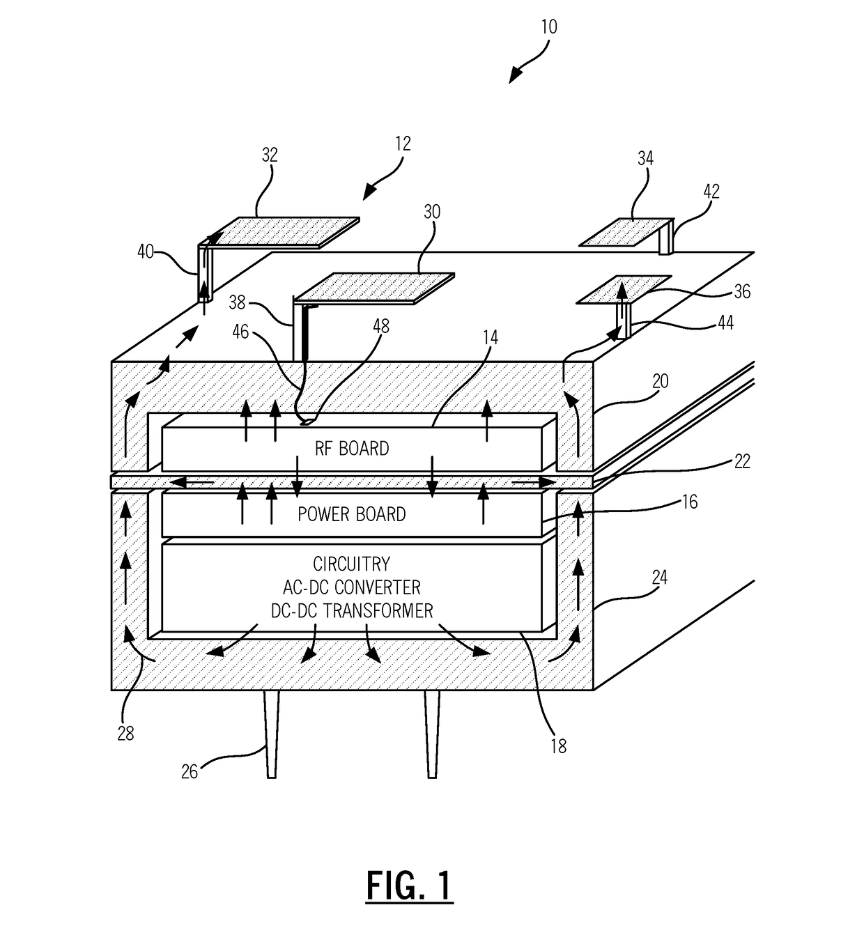
[0040]In various exemplary embodiments, the present disclosure relates to an antenna structure incorporated in a heat spreader, heat sink, and / or cooling fins, such as for use in a high-density wireless device including a wireless Access Point (AP). In general, the device described herein reuses heat spreaders / heat sinks as part of the antenna, uses antenna elements as cooling fins, and reuses the heat sinks as dense Radio Frequency (RF), Electromagnetic Interference (EMI), and Electromagnetic Compatibility (EMC) shield, box, or Faraday cage for other components in the device. In an exemplary embodiment, the antenna structure can be used in a small form-factor, high-density wireless Access Point (AP); however, those skilled in the art will recognize other devices are also contemplated. The foregoing descriptions describe various approaches to adapting to the limitations of reused metal for antenna purposes.

[0041]As described herein, the metallic components of the device can include,...


PUM


Abstract

An antenna system reusing metallic components in a device includes a first antenna element which is also configured to transfer heat into surrounding air; a ground plane which is part of reused metallic components in the device for heat dissipation; and a first physical connection between the first antenna element and the ground plane which supports thermal conductivity based on an associated size and material of the first physical connection.

Description

FIELD OF THE DISCLOSURE[0001]The present disclosure generally relates to antenna systems and methods. More particularly, the present disclosure relates to an antenna structure incorporated in a heat spreader, heat sink, and / or cooling fins, such as for use in a high-density, high-integrated wireless device including a wireless Access Point (AP).BACKGROUND OF THE DISCLOSURE[0002]Various devices utilize antennas for wireless communication, such as mobile phones, wireless Access Points (APs), laptops, tablets, and the like. Conventionally, antennas are included in such devices with adequate clearance between the antenna elements and associated metallic components in the device. However, a trend in device design is the drive by industrial design to build form factors that are appealing to consumers. In the past, engineering drove product form factor, and this worked well with the requirement to clear antenna elements from metallic components. With the trend towards appealing form factor...

Claims


Application Information

Patent Timeline
IPC IPC(8): H01Q1/02H01Q1/48H01Q1/24H01Q5/30
CPCH01Q1/02H01Q5/30H01Q1/246H01Q1/48H01Q1/007H01Q1/36H01Q1/38H01Q1/44H01Q9/42H01Q13/106H01Q21/065H01Q21/28
Inventor SAMARDZIJA, MIROSLAVMCFARLAND, WILLIAMLIEW, JEFFREY CHIFAIHANLEY, PATRICKMALKIN, YOSEPHCHANG, RICHARD TZEWEINGUYEN, DUC MINHVO, LIEM HIEU DINH
Owner PLUME DESIGN INC
Why Eureka
Try Eureka