Automotive rotary electric machine

a rotary electric machine and electric motor technology, applied in the direction of mechanical energy handling, magnetic circuit rotating parts, magnetic circuit shape/form/construction, etc., can solve the problem of not considering suppressing magnetic leakage flux, and achieve the effect of reducing the radial dimensions of the rotor, increasing the effective magnetic flux, and improving outpu

Active Publication Date: 2018-11-29
MITSUBISHI ELECTRIC CORP
View PDF7 Cites 2 Cited by
  • Summary
  • Abstract
  • Description
  • Claims
  • Application Information

AI Technical Summary

Benefits of technology

[0007]According to the present invention, a circumferentially tapered portion is formed on a circumferential shoulder portion of at least one magnetic pole portion of first magnetic pole portions and second magnetic pole portions that face each other in a circumferential direction, and a portion of the circumferentially tapered portion enters a region in which a second side surface and a first side surface that face each other in the circumferential direction overlap when viewed from a direction that is perpendicular to the first side surface and the second side surface. Thus, magnetic leakage flux that flows between the first magnetic

Problems solved by technology

However, in conventional automotive rotary electric machines, no consideration has been given to suppr

Method used


Image

  • Automotive rotary electric machine
  • Automotive rotary electric machine
  • Automotive rotary electric machine

Examples


embodiment 1

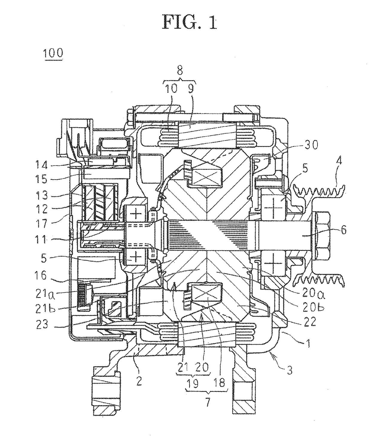
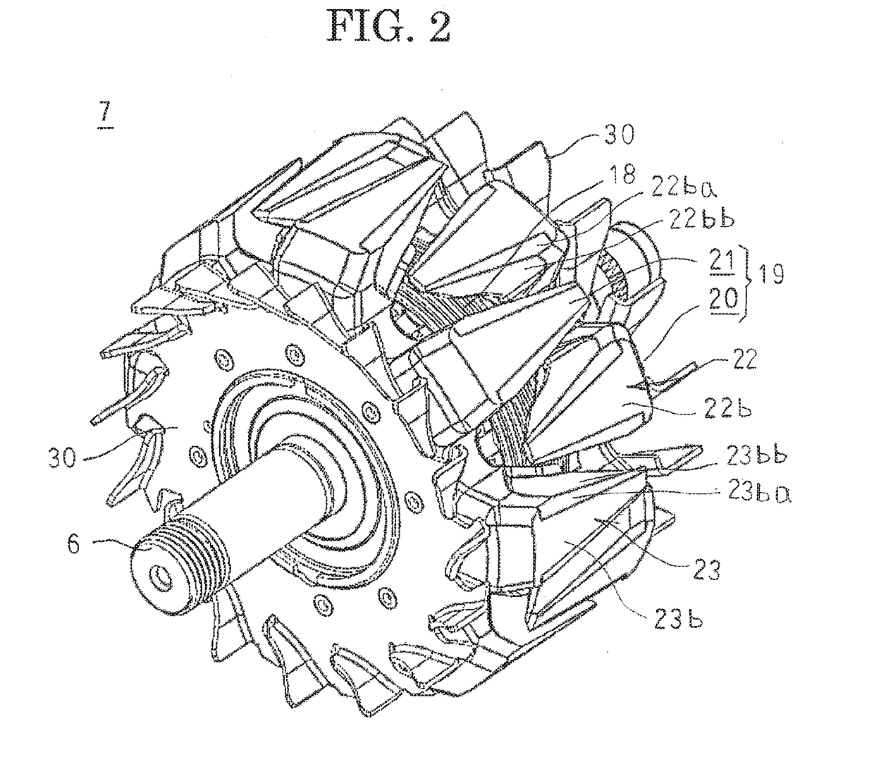
[0020]FIG. 1 is a cross section that shows an automotive alternator according to Embodiment 1 of the present invention, and FIG. 2 is an oblique projection that shows a rotor of the automotive alternator according to Embodiment 1 of the present invention. Moreover, to facilitate explanation, “an axial direction” is an axial direction of the rotating shaft, “a radial direction” is a radial direction of the rotating shaft, and “a circumferential direction” is a direction of rotation of the rotating shaft.

[0021]In FIGS. 1 and 2, an automotive alternator 100 that constitutes an automotive rotary electric machine includes: a case 3 that is constituted by a front bracket 1 and a rear bracket 2 that are made of aluminum; a Lundell rotor 7 that is housed inside the case 3 so as to be fixed to a rotating shaft 6 that is supported in the front bracket 1 and the rear bracket 2 by means of bearings 5; and a stator 8 that has an annular stator core 9 and a stator coil 10 that is mounted to the s...


PUM


Abstract

First side surfaces 22bb of first magnetic pole portions 22b and second side surfaces 23bb of second magnetic pole portions 23b that face each other in a circumferential direction are configured into parallel flat surfaces, first circumferentially tapered portions 25b are formed on circumferential shoulder portions of the first magnetic pole portions 22b, second circumferentially tapered portions 26b are formed on circumferential shoulder portions of the second magnetic pole portions 23b, and portions of the first and second circumferentially tapered portions 25b and 26b enter a region 24 in which the first side surfaces 22bb and the second side surfaces 23bb that face each other in the circumferential direction overlap when viewed from a direction that is perpendicular to the first side surfaces 22bb and the second side surfaces 23bb.

Description

BACKGROUND OF THE INVENTION1. Field of the Invention[0001]The present invention relates to an automotive rotary electric machine that includes a Lundell rotor.2. Description of the Related Art[0002]In conventional automotive dynamoelectric machines that have a Lundell rotor, circumferentially tapered portions are formed on shoulder portions of magnetic pole portions of claw-shaped magnetic poles that are positioned forward in a direction of rotation to reduce unpleasant wind noise that has high-order harmonic components (see Patent Literature 1, for example).CITATION LISTPatent Literature[0003]Patent Literature 1: Japanese Patent No. 3929615 (Gazette)SUMMARY OF THE INVENTION[0004]In automotive rotary electric machines of this kind, in order to achieve compactness and high output, it is important to improve the amount of effective magnetic flux, which is the amount of magnetic flux that interlinks with a stator coil among the magnetic flux that is generated by a rotor. In order to im...

Claims


Application Information

Patent Timeline
IPC IPC(8): H02K1/24
CPCH02K1/243H02K3/18H02K9/06H02K1/12H02K1/145H02K1/26H02K5/04H02K7/1008H02K11/33H02K2213/03H02K1/14H02K1/24H02K7/10H02K19/22
Inventor IMAZAWA, YOSHIROUESATO, YUKI
Owner MITSUBISHI ELECTRIC CORP
Why Eureka
Try Eureka