
Method of laminating ultra-thin glass to non-glass substrates

Inactive Publication Date: 2018-12-06
CORNING INC
View PDF3 Cites 14 Cited by
  • Summary
  • Abstract
  • Description
  • Claims
  • Application Information

AI Technical Summary

Benefits of technology

The patent text describes a method for making a laminate structure by assembling a stack of glass and non-glass substrates with an interlayer in between. The interlayer has a higher glass transition temperature and coefficient of thermal expansion than the substrates, and the non-glass substrate has a softening point. The stack is heated to a temperature between the glass transition temperature of the interlayer and the softening point of the non-glass substrate to bond the substrates together. A force is applied to the substrates to counteract thermal stress and polymer cure forces during bonding. The resulting laminate structure has a flat surface and a compressive stress. The method can be used to make warp-free laminate structures with intended compressive stress.

Problems solved by technology

A limitation in providing such laminates utilizing ultra-thin glass substrates is that when such products are produced on a large scale utilizing large surface areas and thicker substrates, many manufacturing challenges arise.
Additionally, plastic and polymer softening temperatures versus adhesive high temperature bond and cure temperature requirements compete and cause warp, distortion, bubbles and / or breakage in the finished glass-plastic laminates and in ultra-thin glass-metal laminates of certain thicknesses.

Method used


Image

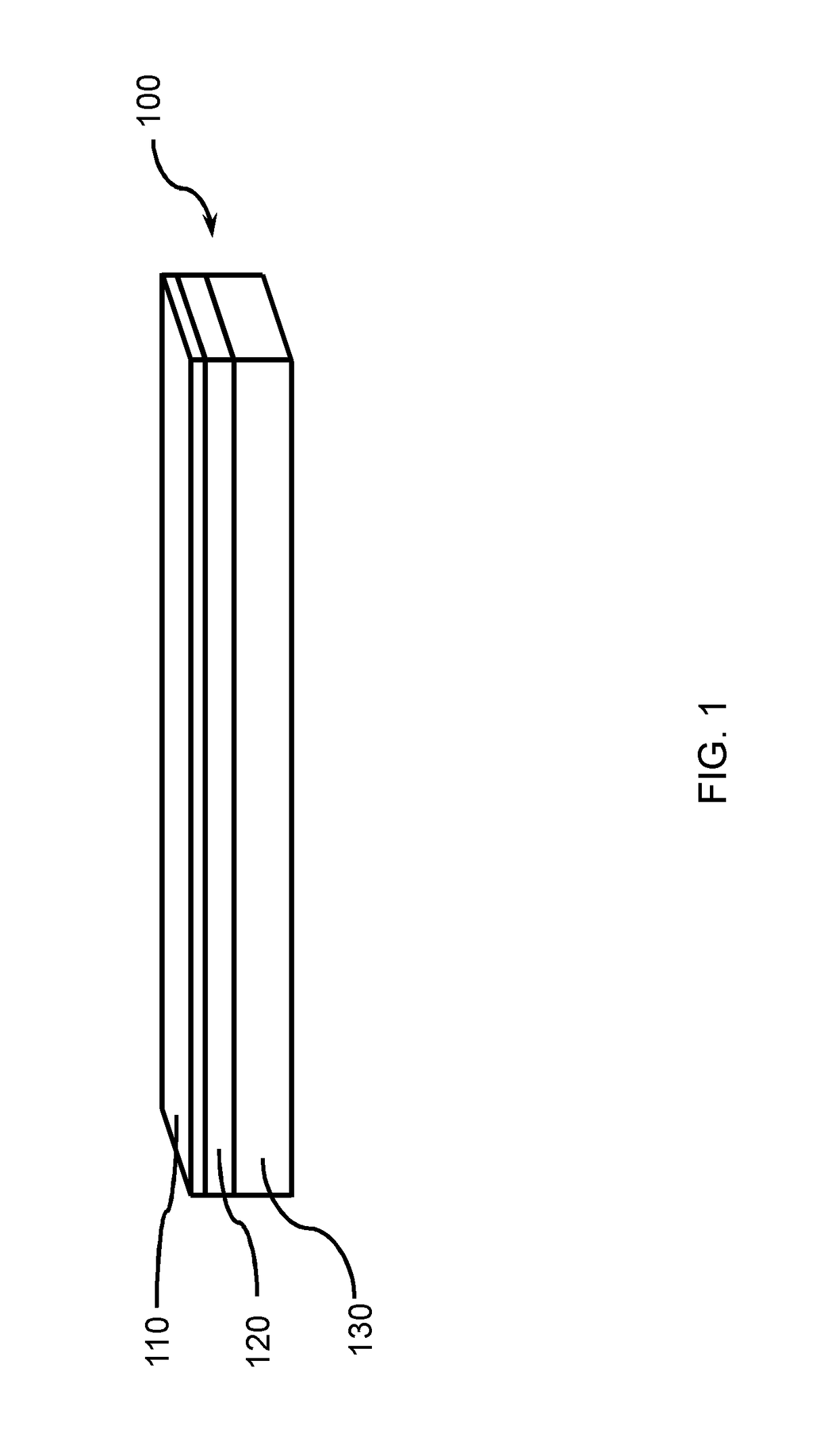
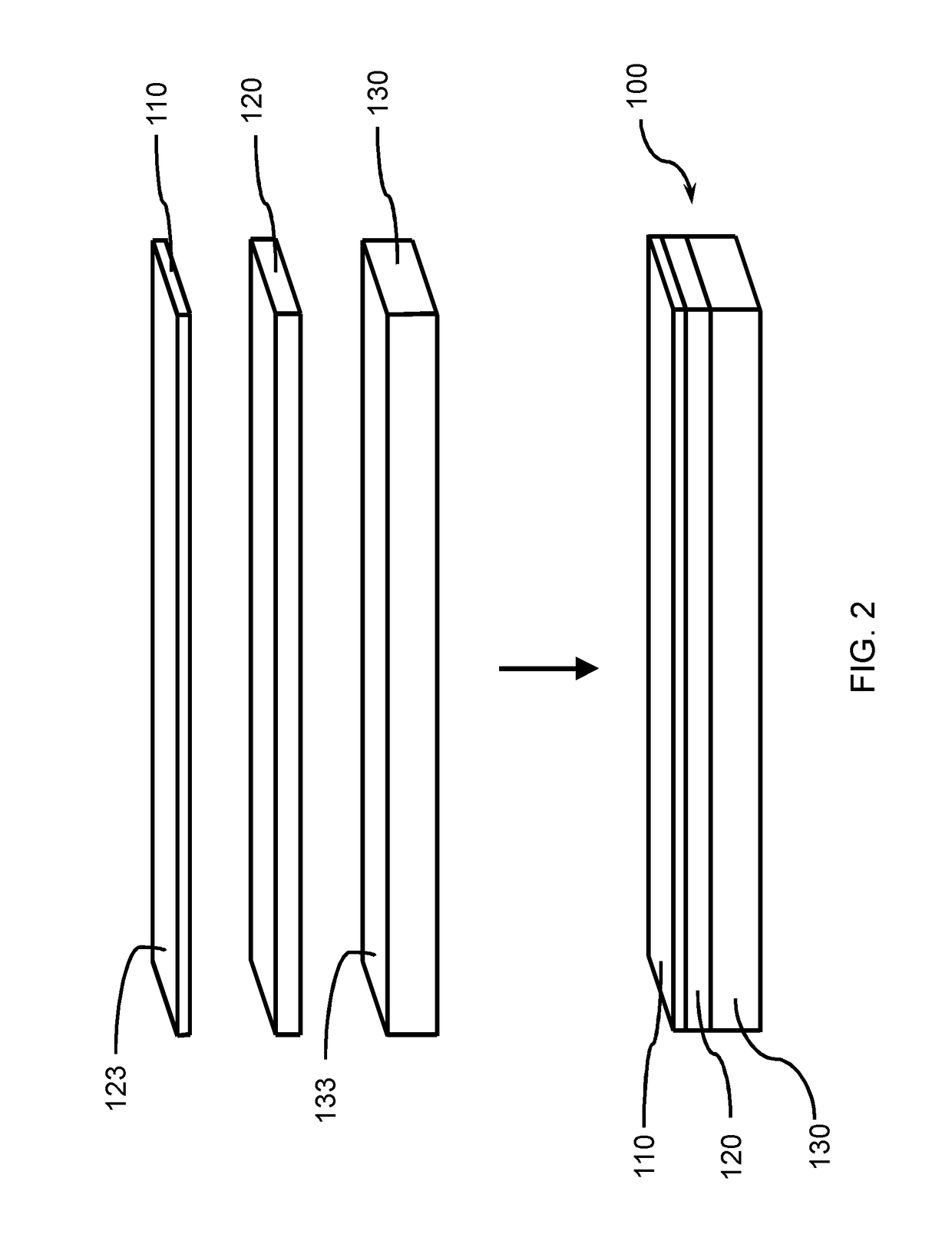
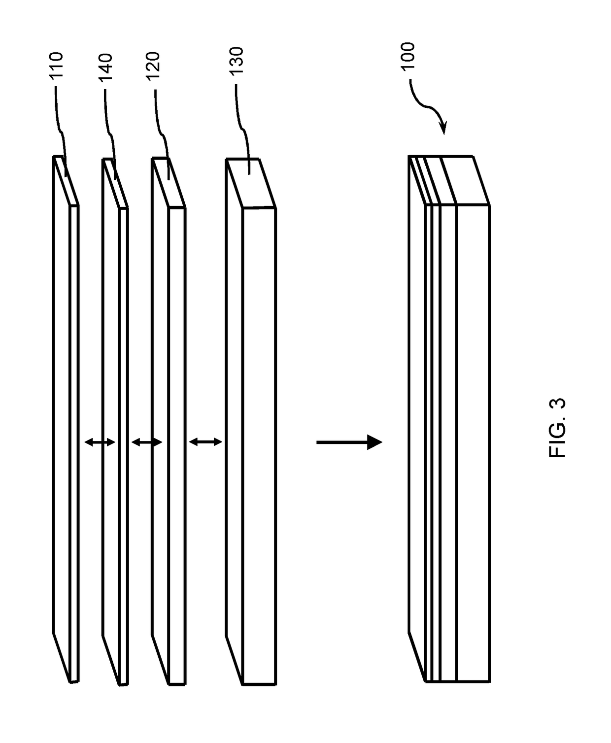
  • Method of laminating ultra-thin glass to non-glass substrates
  • Method of laminating ultra-thin glass to non-glass substrates
  • Method of laminating ultra-thin glass to non-glass substrates

Examples


example 1

[0076]In a non-limiting example of a method of forming a laminate structure, a first glass tray, which is made of chemically strengthened glass, was positioned in a horizontal orientation to provide a first uniform, flat, rigid surface. The first horizontal glass tray was a bottom glass tray having an exposed top surface. A polymer sheet, which was a polytetrafluoroethylene, was positioned upon at least a portion of the bottom glass tray to provide a barrier between the exposed top surface of the bottom glass tray and a surface of a glass substrate or non-glass substrate. A single polymer sheet covered the entire surface of the bottom glass tray, or a single polymer sheet covered only a portion of the bottom glass sheet upon which laminate structures are to be formed, or a plurality of polymer sheets were arrayed over the exposed top surface of the bottom glass tray to provide positions for placement of a plurality of individual laminate structures. A glass substrate or a non-glass ...

example 2

[0078]In another non-limiting example of a method of forming a laminate structure, the stack was bonded together during a bond cycle, and then the interlayer was cured during a cure cycle to achieve defect and warpage free laminate structure.

[0079]In a bond cycle, a stack was assembled and placed within a vacuum bag or vacuum ring, and the gas (e.g., air, nitrogen, argon, etc.) removed from within the vacuum bag or vacuum ring to create an applied pressure equal to atmospheric pressure on at least the major surfaces of the stack. The temperature of the stack, as measured by a sensor, was increased from room temperature to a maximum intended temperature of 120° C. at a rate of about 2.8° C. / min. over approximately 35 minutes, while the vacuum bag or vacuum ring was maintained under a vacuum and a force was applied to the stack. The stack was maintained at a temperature of about 120° C., which is less than the softening temperature of the non-glass structure and a pressure of approxim...


PUM

PropertyMeasurementUnit
Temperatureaaaaaaaaaa
Thicknessaaaaaaaaaa
Thicknessaaaaaaaaaa

Abstract

Embodiments of the present disclosure relate generally to methods of forming a laminate structure. In one or more embodiments, the method includes situating an interlayer between a glass substrate and a non-glass substrate having a softening point to form an assembled stack, heating the assembled stack to a temperature in a range of greater than the Tg of the interlayer to less than the softening point of the non-glass substrate and applying a force to at least one of the laminate glass surface and the laminate non-glass surface to bond that counter-balances thermal stress and polymer cure forces during bonding and prevents warpage, distortion and breakage of the laminate. In some embodiments, the interlayer has a coefficient of thermal expansion (CTE) at least 10 times greater than the CTE of the glass substrate.

Description

CROSS-REFERENCE TO RELATED APPLICATIONS[0001]This application claims the benefit of priority under 35 U.S.C. § 119 of U.S. Provisional Application Ser. No. 62 / 246,806 filed on Oct. 27, 2015 the content of which is relied upon and incorporated herein by reference in its entirety.TECHNICAL FIELD[0002]Principles and embodiments of the present disclosure relate generally to methods of forming a laminate structure by bonding an ultra-thin glass substrate to a non-glass substrate with an interlayer at temperatures greater than the Tg of the interlayer.BACKGROUND[0003]Lamination processes for laminating glass substrates thicker than 300 microns to non-glass substrates have involved roll lamination, UV cure adhesives and glass-to-glass bonding. Roll lamination utilizes a pressure sensitive adhesive to bond at near room temperature. Room temperature adhesives have been used in such processes using glass substrates thicker than 300 microns to form various glass to non-glass laminates.[0004]Th...

Claims


Application Information

Patent Timeline
IPC IPC(8): B32B37/14B32B17/06B32B17/10B32B37/00
CPCB32B37/144B32B17/061B32B17/064B32B17/10018B32B17/10743B32B17/10761B32B17/1077B32B17/10788B32B37/0015B32B2037/1253B32B2307/30B32B2309/02B32B17/10B32B17/10137B32B17/10816B32B37/1009B32B2309/105
Inventor KANG, KIAT CHYAILEWIS, SUE CAMILLENATARAJAN, GOVINDARAJANPARK, MARIANNE GRIESBACHWETMORE, NATHANIEL DAVID
Owner CORNING INC
Learn More