
Lattice structure in cooling pathway by additive manufacture

a technology of additive manufacturing and cooling pathway, which is applied in the manufacture of engines, mechanical equipment, machines/engines, etc., can solve the problems of unfavorable temperature-dependent properties, fatigue and/or damage, and the effect of unfavorable cooling

Inactive Publication Date: 2018-12-06
GENERAL ELECTRIC CO
View PDF3 Cites 5 Cited by
  • Summary
  • Abstract
  • Description
  • Claims
  • Application Information

AI Technical Summary

Benefits of technology

This patent is about a new design for components used in industrial machines that are exposed to high temperatures. The design includes a layer of thermal barrier coating on the outer surface of the component, an internal cooling circuit, and a lattice structure at the outer surface that allows a cooling medium to pass through in response to any spalls in the thermal barrier coating that may occur. This design can be manufactured using additive manufacturing techniques and can help improve the efficiency and durability of components in hot gas paths.

Problems solved by technology

Insufficient cooling may result in undo stress and oxidation on the airfoil and may lead to fatigue and / or damage.
Specifically, the component may have temperature dependent properties that may be adversely affected by overheating.
As a result, many hot gas path components may be overcooled to compensate for localized hot spots that may develop on the components.
Such excessive overcooling, however, may have a negative impact on overall industrial machine output and efficiency.
If a break or crack, referred to as a spall, occurs in a TBC of a hot gas path component, the local temperature of the component at the spall may rise to a harmful temperature.
Formation of the plug however is complex, requiring precise machining and / or precise thermal or chemical processing of materials to create the plug.

Method used


Image

  • Lattice structure in cooling pathway by additive manufacture
  • Lattice structure in cooling pathway by additive manufacture
  • Lattice structure in cooling pathway by additive manufacture

Examples


Embodiment Construction

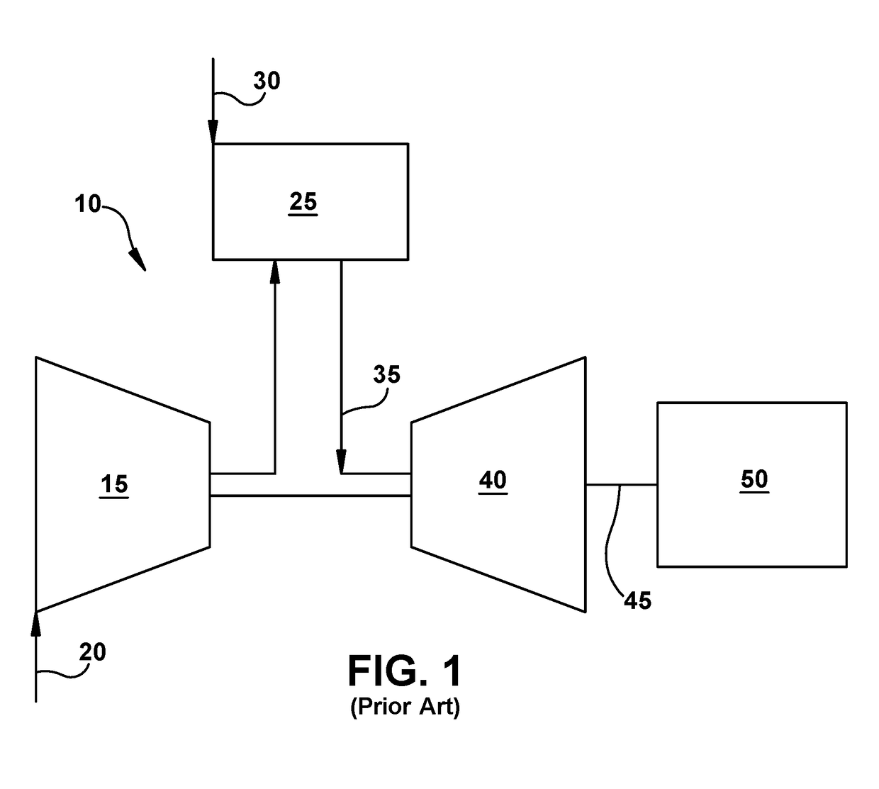
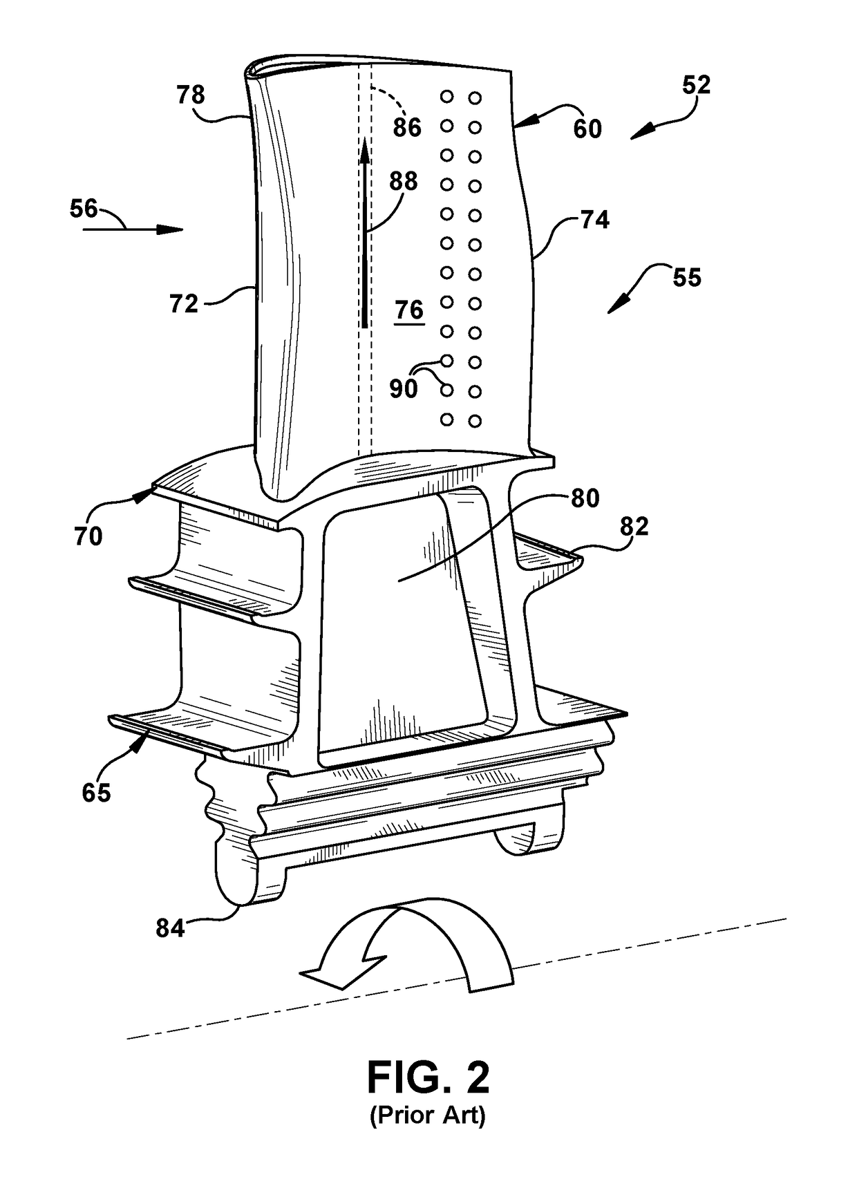
[0023]As an initial matter, in order to clearly describe the current disclosure it will become necessary to select certain terminology when referring to and describing relevant machine components within an industrial machine such as a gas turbine system. When doing this, if possible, common industry terminology will be used and employed in a manner consistent with its accepted meaning. Unless otherwise stated, such terminology should be given a broad interpretation consistent with the context of the present application and the scope of the appended claims. Those of ordinary skill in the art will appreciate that often a particular component may be referred to using several different or overlapping terms. What may be described herein as being a single part may include and be referenced in another context as consisting of multiple components. Alternatively, what may be described herein as including multiple components may be referred to elsewhere as a single part.

[0024]In addition, sev...


PUM

PropertyMeasurementUnit
temperatureaaaaaaaaaa
lattice structureaaaaaaaaaa

Abstract

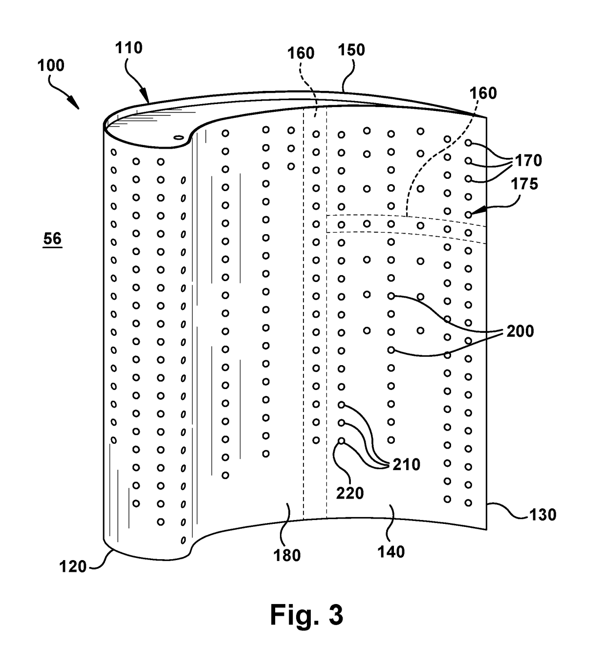
A hot gas path component of an industrial machine includes a cooling pathway with a lattice structure therein. The component and lattice structure are made by additive manufacturing. The component includes an outer surface exposed to a working fluid having a high temperature; a thermal barrier coating over the outer surface; an internal cooling circuit; and a cooling pathway in communication with the internal cooling circuit and extending towards the outer surface. A lattice structure is in the cooling pathway at the outer surface. The lattice structure is configured to support the thermal barrier coating over the cooling pathway and in response to a spall in the thermal barrier coating occurring over the cooling pathway, allow a cooling medium from the internal cooling circuit to pass therethrough.

Description

GOVERNMENT CONTRACT[0001]This invention was made with government support under contract number DE-FE0023965 awarded by the U.S. Department of Energy. The government has certain rights in the invention.BACKGROUND OF THE INVENTION[0002]The disclosure relates generally to cooling of components, and more particularly, to a cooling pathway of a hot gas path component that is made by additive manufacturing, and includes a lattice structure therein.[0003]Hot gas path components that are exposed to a working fluid at high temperatures are used widely in industrial machines. For example, a gas turbine system includes a turbine with a number of stages with blades extending outwardly from a supporting rotor disk. Each blade includes an airfoil over which the hot combustion gases flow. The airfoil must be cooled to withstand the high temperatures produced by the combustion gases. Insufficient cooling may result in undo stress and oxidation on the airfoil and may lead to fatigue and / or damage. T...

Claims


Application Information

Patent Timeline
Patent Type & Authority Applications(United States)
IPC IPC(8): F01P1/02F01P5/06F01P11/10F02B29/04
CPCF01P1/02F01P5/06F01P11/10F01D5/18B33Y10/00F01D5/183F01D5/186F02B29/0456B22F10/28F01D5/288F05D2260/202F05D2270/46F05D2250/28F05D2300/50B22F5/00F05D2300/612F05D2300/514F05D2300/613B22F5/10B33Y80/00Y02P10/25Y02T10/12F01D5/187F05D2230/90
Inventor LACY, BENJAMIN PAULMORGAN, VICTOR JOHN
Owner GENERAL ELECTRIC CO
Learn More