Liquid crystal display device

a display device and liquid crystal technology, applied in the field of liquid crystal display devices, can solve problems such as difficulty in mass production, and achieve the effect of high stability

a display device and liquid crystal technology, applied in the field of liquid crystal display devices, can solve problems such as difficulty in mass production, and achieve the effect of high stability

US20180356663A1Inactive Publication Date: 2018-12-13WUHAN CHINA STAR OPTOELECTRONICS TECH CO LTD

Image

  • Liquid crystal display device

Examples


Embodiment Construction

[0021]Please refer to figures, wherein the same assembly symbol represents the same assembly. The principles of the present disclosure are exemplified by implementation in a suitable computing environment. The following description is based on the specific embodiments of the present disclosure illustrated, and should not be construed as limiting other specific embodiments of the present disclosure which are not detailed herein.

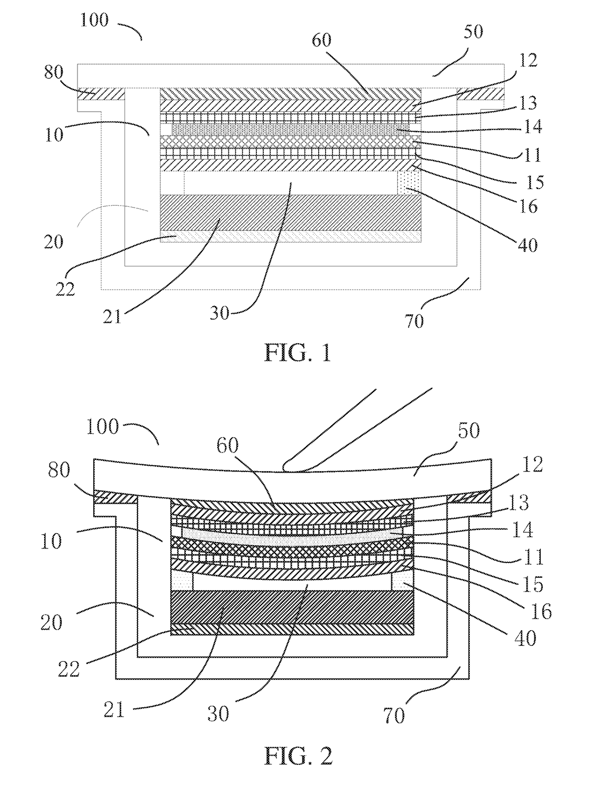
[0022]Please refer to FIG. 1 and FIG. 2, wherein FIG. 1 is a schematic view of a preferred embodiment of the liquid crystal display device of the present disclosure in a non-pressing state, and FIG. 2 is a schematic view of a preferred embodiment of the liquid crystal display device of the present disclosure in a pressing state. The liquid crystal display device 100 of the present disclosure includes a liquid crystal display panel 10, a backlight module 20, an adhesive frame 40, a protecting glass 50, an OCA optical adhesive 60, a middle frame 70, and an adhes...


PUM


Abstract

A liquid crystal display device is disclosed in the present disclosure, which includes a liquid crystal display panel and a backlight module, with a gap disposed between the liquid crystal display panel and the backlight module, wherein the liquid crystal display panel includes an array substrate including a touch force sensing electrode disposed thereupon, the backlight module includes a backlight source and a metal backplane disposed on a bottom of the backlight source, and a touch force sensing capacitor of the liquid crystal display device is composed of the touch force sensing electrode and the metal backplane.

Description

FIELD OF THE INVENTION[0001]The present disclosure relates to the technical field of liquid crystal display devices, and particularly to a liquid crystal display device with a new embedded force touch technology.BACKGROUND OF THE INVENTION[0002]Force touch technology has now begun to gradually apply to consumer products such as mobile phones, tablets, and so on. It has been classified into types of piezo-resistive, piezo-electric, and capacitive based on the operational principle, with the capacitive technology being relatively mature and the most widely used. According to different positions of a touch sensing electrode among the capacitive force touch panels, the capacitive force touch panels can be divided into a conventional force touch technology and a new embedded force touch technology. Whether the technology is the conventional technology or new capacitive force touch technology, both need another sensor electrode (must be connected to GND) in addition to the force touch sen...

Claims


Application Information

Patent Timeline
13 Dec 2018
Publication
US20180356663A1
IPC
G02F1/1333; G02F1/1362; G06F3/041
CPC
G02F1/13338; G02F1/136286; G06F3/0412; G06F3/0414; G02F2001/133331; G02F2202/28; G02F2001/133317; G02B6/0081
Inventors
ZHANG, HONGSEN; HUANG, YAO-LI