
Optimized shadows in a foveated rendering system

a rendering system and shadow technology, applied in image generation, image rendering, instruments, etc., can solve the problems of user being denied the full gaming experience of higher resolution graphics, the wireless connection may not be robust enough to handle the required bandwidth, and the high-powered graphics processor providing an unbelievably viewing and interactive experien

Active Publication Date: 2018-12-13
SONY COMPUTER ENTERTAINMENT INC
View PDF7 Cites 45 Cited by
  • Summary
  • Abstract
  • Description
  • Claims
  • Application Information

AI Technical Summary

Benefits of technology

The present patent relates to a technology that displays parts of an image with high and low resolution. It uses a shadow map of high resolution for displaying shadows in the foveated region and a shadow map of lower resolution for displaying shadows outside the foveated region. This reduces the bandwidth required for displaying video frames and allows for real-time delivery without latency due to reduced computation complexity.

Problems solved by technology

For example, high powered graphics processors provide an unbelievably viewing and interactive experience when playing a video game.
However, gaming systems increasingly are configured with a wireless connection that may provide a bottleneck when pushing data to the display.
In these cases, the wireless connection may not be robust enough to handle the required bandwidth to fully take advantage of the higher resolution displays, such that the video game as displayed may be interrupted (as the buffer is filling up) in order to display the entire video sequence as rendered.
In some cases, the video game processing may be throttled in order to match the lower bandwidth of the wireless connection to the display, such that the video frames may be rendered at lower resolutions in order to push video data over the wireless connection without interruption; however, by throttling the processing, the user is denied the full gaming experience with higher resolution graphics.

Method used


Image

  • Optimized shadows in a foveated rendering system
  • Optimized shadows in a foveated rendering system
  • Optimized shadows in a foveated rendering system

Examples


Embodiment Construction

[0026]Although the following detailed description contains many specific details for the purposes of illustration, anyone of ordinary skill in the art will appreciate that many variations and alterations to the following details are within the scope of the present disclosure. Accordingly, the aspects of the present disclosure described below are set forth without any loss of generality to, and without imposing limitations upon, the claims that follow this description.

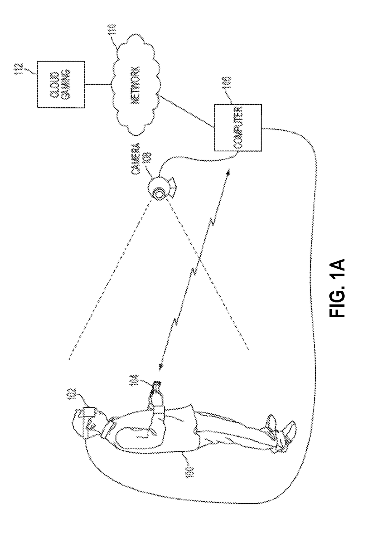
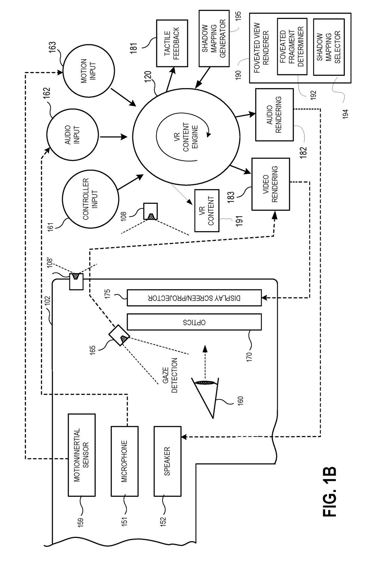
[0027]Generally speaking, the various embodiments of the present disclosure describe a graphics processor of a video rendering system that is configured to perform foveated rendering, wherein portions of images in a foveal region may be rendered with high resolution and portions outside the foveal region may be rendered with lower resolution. In particular, shadowing of objects that are displayed inside the foveal region are rendered using a shadow map of higher resolution, and the shadowing of objects that re displayed...


PUM


Abstract

A method for implementing a graphics pipeline. The method includes building a first shadow map of high resolution, and building a second shadow map based on the first shadow map of lower resolution. The method includes determining a light source affecting a virtual scene, and projecting geometries of objects of an image of the virtual scene onto a plurality of pixels of a display from a first point-of-view. The method includes determining a foveal region when rendering the image, wherein the foveal region corresponds to where an attention of a user is directed. The method includes determining a first set of geometries is drawn to a first pixel, determining the first set of geometries is in shadow based on the light source, and determining the first set of geometries is outside of the foveal region. The method includes rendering the first set of geometries using the second shadow map.

Description

CLAIM OF PRIORITY[0001]The present application claims priority to and the benefit of the commonly owned, provisional patent application, U.S. Ser. No. 62 / 517,829, filed on Jun. 9, 2017, entitled “OPTIMIZED SHADOWS IN A FOVEATED RENDERING SYSTEM,” which is herein incorporated by reference in its entirety.TECHNICAL FIELD[0002]The present disclosure is related to video games or gaming applications. Among other things, this disclosure describes methods and systems for selecting appropriate shadowing of objects in a foveated rendering system.BACKGROUND OF THE DISCLOSURE[0003]Video gaming has increasingly become more popular with the advancement of video game technology. For example, high powered graphics processors provide an unbelievably viewing and interactive experience when playing a video game. In addition, displays are being designed with higher and higher resolutions. For example, present technology includes displays having 2K resolution (e.g., 2.2 megapixels over 2048×1080 pixels...

Claims


Application Information

Patent Timeline
Patent Type & Authority Applications(United States)
IPC IPC(8): G06T7/66G06T7/00G06T7/20G06T7/73G06T11/20G06T13/80
CPCG06T7/66G06T7/0002G06T7/20G06T7/73G06T11/20G06T13/80G06T11/40G06F3/012G06F3/013G06T2215/12G06T15/10G06T2210/36
Inventor YOUNG, ANDREWHO, CHRISSTAFFORD, JEFFREY ROGER
Owner SONY COMPUTER ENTERTAINMENT INC
Learn More