Cantilevered vane and gas turbine including the same

a technology of cantilever vane and gas turbine, which is applied in the direction of blade accessories, engine fuctions, machines/engines, etc., can solve the problems of increased vibration, vibration rubbing, and inability to stabilize the vane hub

Active Publication Date: 2018-12-20
DOOSAN HEAVY IND & CONSTR CO LTD
View PDF8 Cites 3 Cited by
  • Summary
  • Abstract
  • Description
  • Claims
  • Application Information

AI Technical Summary

Benefits of technology

[0009]Accordingly, it is an object of the present invention to provide a cantilevered vane having a structure that can contribute to the vibration stability of a vane hub.
[0010]It is another object of the present invention to provide a cantilevered vane having a stable structure that improves the efficiency of cooling an airfoil.
[0019]The airfoil may be provided with at least two exhaust holes communicating with the second channel, so that a portion of the cooling fluid flowing through the second channel can be discharged from the airfoil. The exhaust holes may be formed at one end of the airfoil and have inner diameters that gradually increase in size toward the rear-wing portion of the airfoil. The exhaust holes may have inner diameters that gradually increase in size in a flow direction of the cooling fluid, so that a flow rate of cooling fluid can be adjusted to a predetermined level.

Problems solved by technology

The structure of such a shroud-type vane exhibits a low natural frequency, so there is a possibility of flutter (vibration) in a lower mode of a gas turbine, thereby inducing instability of the vane hub and an increased tendency toward vibration and the rubbing associated with vibration.

Method used


Image

  • Cantilevered vane and gas turbine including the same
  • Cantilevered vane and gas turbine including the same
  • Cantilevered vane and gas turbine including the same

Examples


Embodiment Construction

[0032]Hereafter, embodiments of the present invention will be described in detail with reference to the accompanying drawings. The terms and words used in the present specification and claims should not be interpreted as being limited to typical meanings or dictionary definitions, but should be interpreted as having meanings and concepts relevant to the technical scope of the present invention.

[0033]Throughout the specification, if it is described that a component is formed on another component, a component may be directly provided on another component, or a component may be interposed between components. Through the present specification, unless explicitly described otherwise, “comprising” any components will be understood to imply the inclusion of other components rather than the exclusion of any other components.

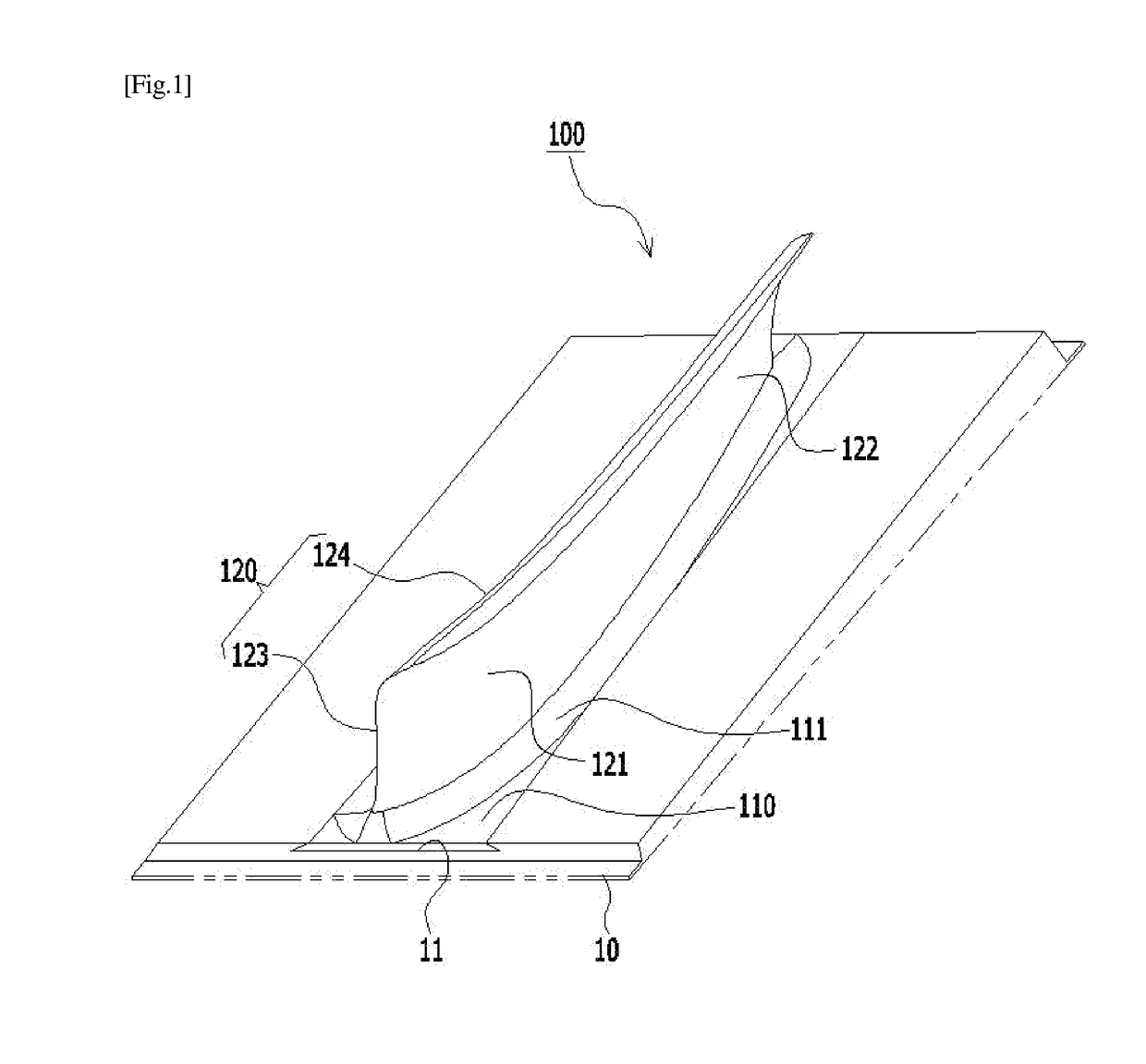
[0034]FIG. 1 shows a cantilevered vane having a J-shaped structure including a front-wing portion and a rear-wing portion according to an embodiment of the present invent...


PUM


Abstract

A cantilevered vane, for use with a rotary disc of a gas turbine, includes a root supported in a dovetail slot formed in a circumferential surface of the rotary disc; and an airfoil protruding a predetermined height from the root and having a J-shaped cross-section throughout a front-wing portion and a rear-wing portion of the airfoil. The airfoil includes a straight portion vertically extending upward from the root by a predetermined height; and a curved portion integrally formed with an upper end of the straight portion to cantilever toward one side of the airfoil, the curved portion being inclined at a predetermined angle with respect to the straight portion. Cooling fluid flows through a first channel formed in the straight portion and a second channel formed in the curved portion. The first channel includes front-wing and rear-wing channels for guiding the cooling fluid to the front-wing and rear-wing portions.

Description

CROSS REFERENCE TO RELATED APPLICATIONS[0001]The present application claims priority to Korean Patent Application No. 10-2017-0077731, filed Jun. 20, 2017, the entire contents of which is incorporated herein for all purposes by this reference.BACKGROUND OF THE INVENTIONField of the Invention[0002]The present invention relates to a cantilevered vane and a gas turbine including the same and, more particularly, to a cantilevered vane having a structure that can reduce airfoil rubbing and can contribute to vibration stability of a vane hub.Description of the Related Art[0003]In general, a turbine is a mechanical device that obtains torque from an impulse or reaction force, using the flow of a compressed fluid such as gas. A device using steam is called a steam turbine and a device using combustion gas is called a gas turbine.[0004]A gas turbine is composed of a compressor, a combustor, and a turbine. The compressor suctions air from the atmosphere, compresses the air, and supplies the c...

Claims


Application Information

Patent Timeline
Patent Type & Authority Applications(United States)
IPC IPC(8): F01D5/18F01D5/30
CPCF01D5/187F01D5/3007F05D2220/32F05D2260/20F01D5/141F01D5/147F01D5/18F01D5/26F01D5/16F01D5/20F01D5/186
Inventor BAEK, SEOL
Owner DOOSAN HEAVY IND & CONSTR CO LTD
Why Eureka
Try Eureka