Machine control for additive manufacturing process and apparatus

Active Publication Date: 2018-12-27
RENISHAW PLC
View PDF0 Cites 22 Cited by
  • Summary
  • Abstract
  • Description
  • Claims
  • Application Information

AI Technical Summary

Benefits of technology

[0011]In this way, the timing of actions of the additive manufacturing apparatus is pre-determined such that accurate calculations and/or simulations for the additive build can be made. In particular, it is possible to accurately calculate a required energy input bas

Problems solved by technology

With such a sequential control system, there is a degree of uncertainty with when each instruction will be executed hindering accurate predictions of the build process.
The uncertainty in the current machine operations is sufficient to make calculating, or simulating, the amount of heat in the workpiece extremely difficult.
However, the uncertainties in the timing of the executions requires an ordering of the commands to include

Method used


Image

  • Machine control for additive manufacturing process and apparatus
  • Machine control for additive manufacturing process and apparatus
  • Machine control for additive manufacturing process and apparatus

Examples


Example

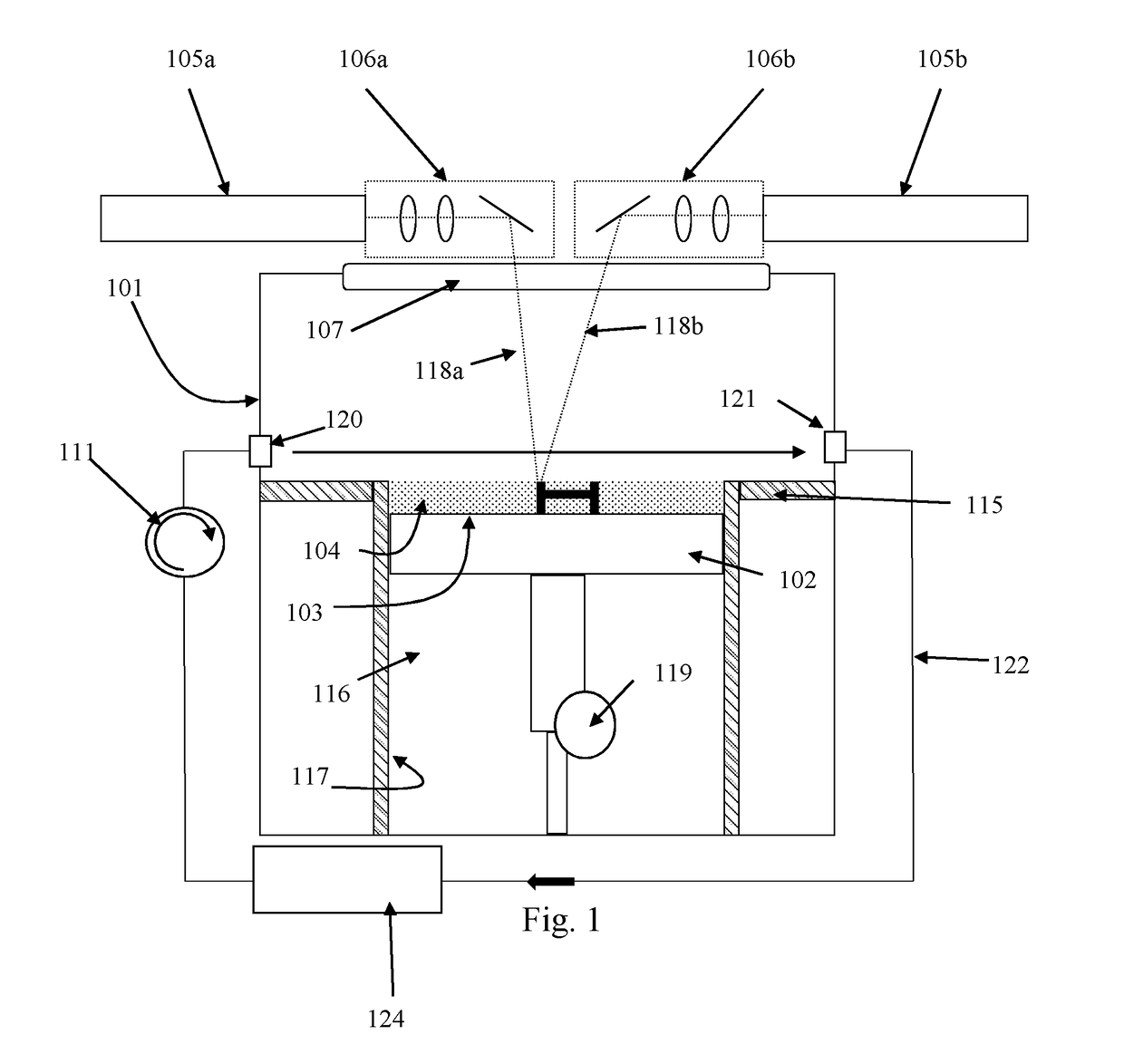
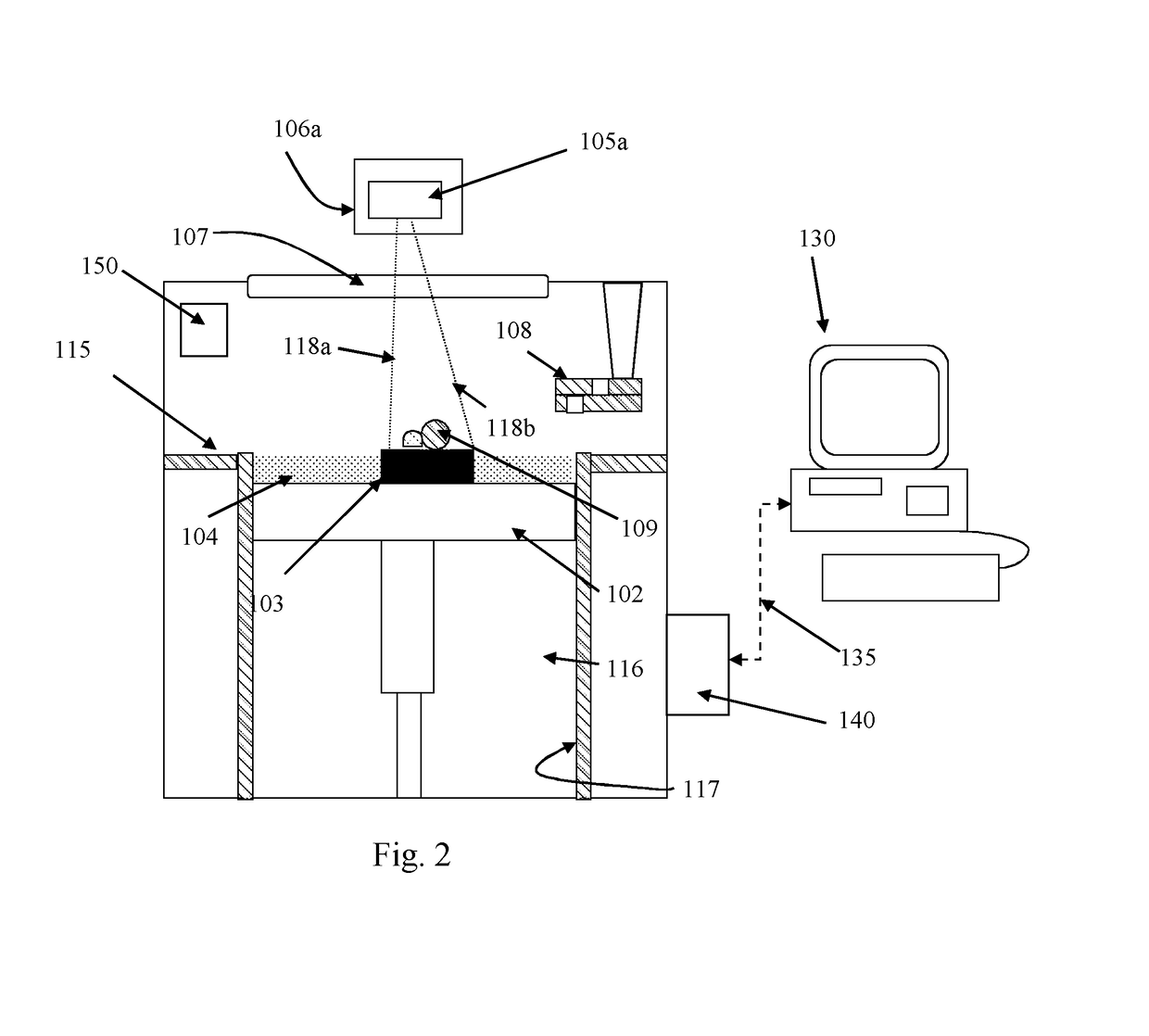
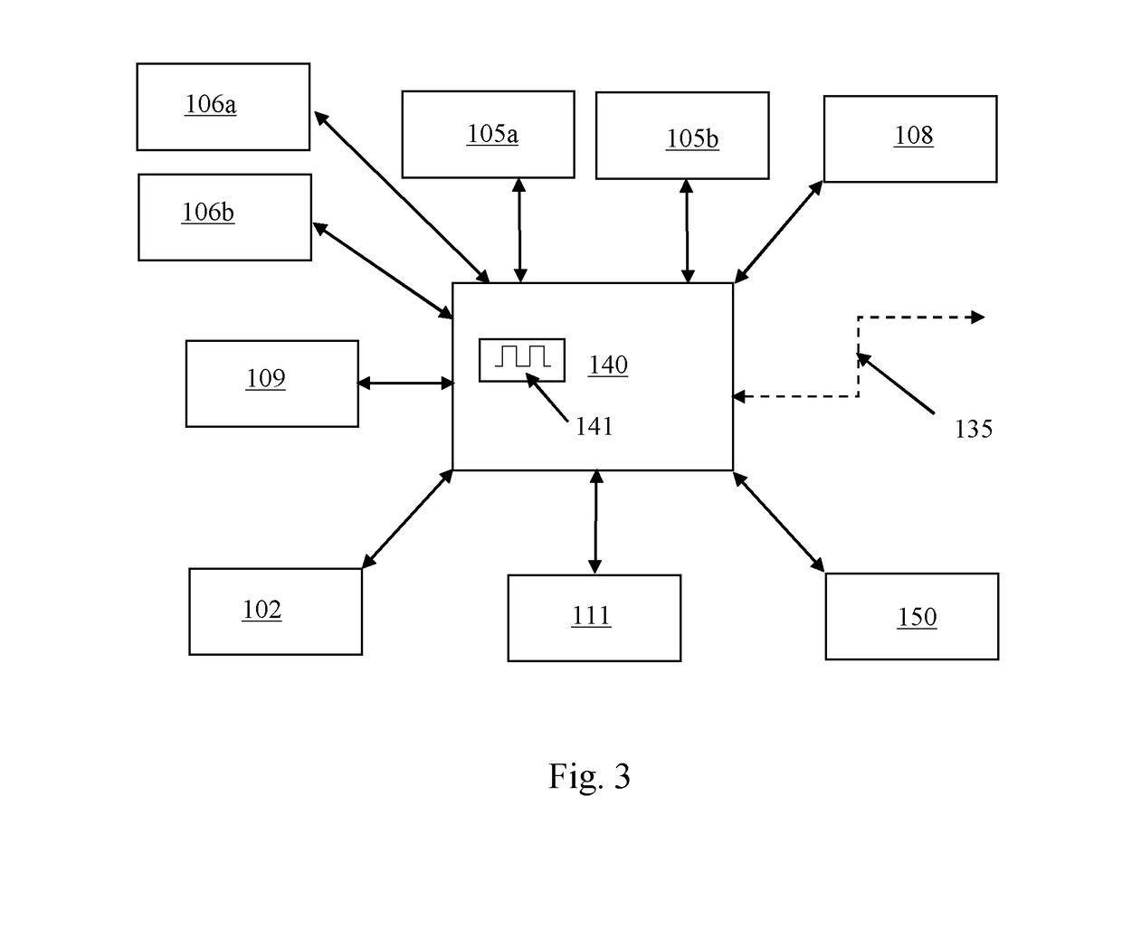
[0060]Referring to FIGS. 1 to 3, an additive manufacturing apparatus according to an embodiment of the invention comprises a main chamber 101 having therein partitions 115, 117 that define a build chamber 116 and a surface onto which powder can be deposited. A build platform 102 is provided for supporting a workpiece 103 built by selective laser melting powder 104. The platform 102 can be lowered within the build chamber 116 under the control of motor 119 as successive layers of the workpiece 103 are formed. A build volume available is defined by the extent to which the build platform 102 can be lowered into the build chamber 116.

[0061]Layers of powder 104 are formed as the workpiece 103 is built by dispensing apparatus 108 and a wiper 109. For example, the dispensing apparatus 109 may be apparatus as described in WO2010 / 007396. A plurality of laser modules, in this embodiment two laser modules 105a, 105b, generate lasers 118a, 118b for melting the powder 104, the lasers 118a, 118b ...


PUM

PropertyMeasurementUnit
Timeaaaaaaaaaa
Energyaaaaaaaaaa

Abstract

A method controls an additive manufacturing apparatus, in which an object is built by consolidating material in a layer-by-layer manner. The method includes receiving commands to be executed by the additive manufacturing apparatus to cause the additive manufacturing apparatus to carry out a build of an object, wherein each command includes an identifier identifying a time during the build at which the command is to be executed, and executing each command on the additive manufacturing apparatus in accordance with the time identified by the associated identifier. Further, an apparatus and a data carrier carry out the method.

Description

FIELD OF INVENTION[0001]This invention concerns machine control and, in a particular, but not exclusively, control of additive manufacturing apparatus, such as material bed (powder or resin bed) additive manufacturing apparatus.BACKGROUND[0002]Additive manufacturing or rapid prototyping methods for producing parts comprise layer-by-layer solidification of a flowable material. There are various additive manufacturing methods, including powder bed systems, such as selective laser melting (SLM), selective laser sintering (SLS), electron beam melting (eBeam) and stereolithography, and non-powder bed systems, such as fused deposition modelling, including wire arc additive manufacturing (WAAM).[0003]In selective laser melting, a powder layer is deposited on a powder bed in a build chamber and a laser beam is scanned across portions of the powder layer that correspond to a cross-section (slice) of the workpiece being constructed. The laser beam melts or sinters the powder to form a solidif...

Claims


Application Information

Patent Timeline
IPC IPC(8): B29C64/393B33Y30/00B33Y50/02B29C64/153B29C64/20
CPCB29C64/393B33Y30/00B33Y50/02B29C64/153B29C64/20B22F10/30B22F12/49B22F10/32B22F10/28B22F12/70B22F12/90B22F10/322Y02P10/25G05B19/4093B22F10/00B22F10/10B33Y10/00B29C64/245B29C64/268
Inventor REVANUR, RAMKUMARBROWN, CERI
Owner RENISHAW PLC
Why Eureka
Try Eureka