Selective powder processing during powder bed additive manufacturing

Active Publication Date: 2018-12-27
GENERAL ELECTRIC CO
View PDF4 Cites 20 Cited by
  • Summary
  • Abstract
  • Description
  • Claims
  • Application Information

AI Technical Summary

Benefits of technology

[0009]These and other aspects of the invention will become more fully

Problems solved by technology

Accordingly, inexpensive replicas of objects may flood the market, and such replicas may be of inferior quality compared to the original, genuine part.
H

Method used


Image

  • Selective powder processing during powder bed additive manufacturing
  • Selective powder processing during powder bed additive manufacturing
  • Selective powder processing during powder bed additive manufacturing

Examples


second embodiment

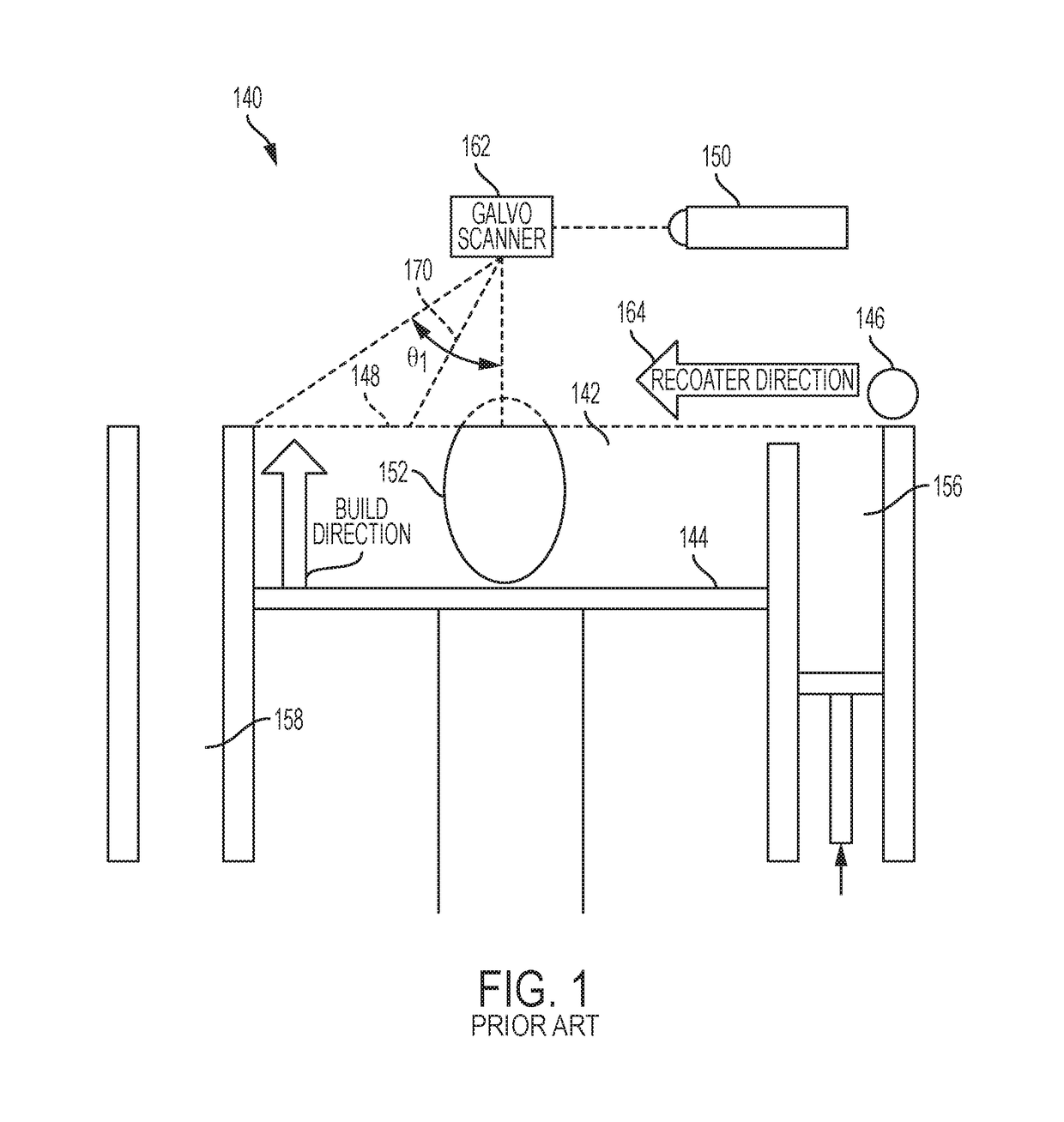
[0072]FIG. 3F shows a close-up view of dispenser unit 280 according to the present disclosure. The dispenser unit 280 shown in FIG. 3F may have identical features to that shown in FIG. 2F. All aspects described with respect to dispenser unit 280 attached to recoater arm 246 (FIG. 2F) apply with equal force to dispenser unit 280 attached to positioning unit 283 (FIG. 3F). The additional vertical movement provided in this embodiment is useful in systems with lowering build plates (e.g., as shown in FIG. 1), as well as in systems with a stationary build plate, including, but not limited to, those described in:

[0073]U.S. patent application Ser. No. 15 / 406,467, titled “Additive Manufacturing Using a Mobile Build Volume,” with attorney docket number 037216.00059, and filed Jan. 13, 2017.

[0074]U.S. patent application Ser. No. 15 / 406,454, titled “Additive Manufacturing Using a Mobile Scan Area,” with attorney docket number 037216.00060, and filed Jan. 13, 2017.

[0075]U.S. patent application ...

third embodiment

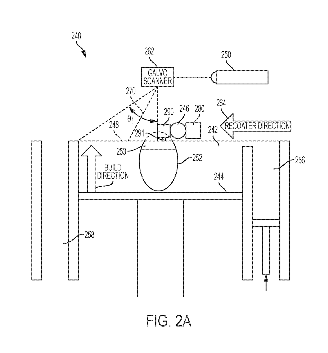
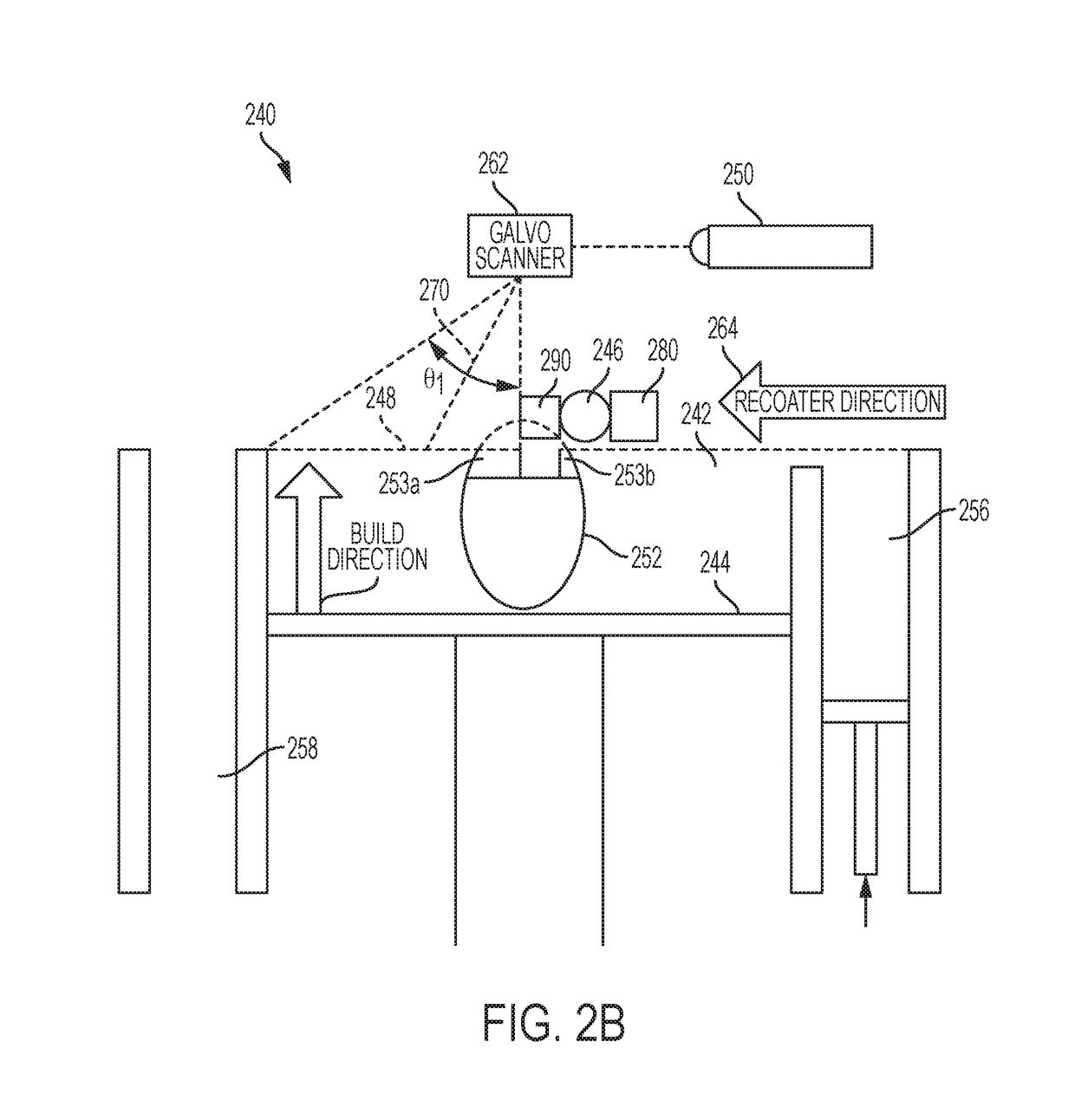
[0095]In a third embodiment, the vacuum unit 290 is attached to a positioning unit 283. The positioning unit may be a motorized robotic arm, e.g. robotic arm 283 of FIG. 4A, separate from the recoater arm 246, and positioning unit 283 is preferably computer-controlled. In an alternative embodiment, the positioning unit 283 may be a gantry, e.g. a X-Y-Z gantry, whereby a plurality of rails or crossbeams, drive belts, drive screws and / or a Cartesian gantry may be utilized to position the vacuum unit 290 close to the powder bed 242. In yet further alternative embodiments, the positioning unit 283 may be a delta robot, a cable robot, a belt drive, or the like. In certain embodiments, vacuum unit 290 attached to a positioning unit 283 may be used in conjunction with other apparatuses and methods for additive manufacturing using multiple build materials, including, but not limited to, methods of making cast components, such as those described in U.S. patent application Ser. No. 15 / 056,703...


PUM

PropertyMeasurementUnit
Dimensionaaaaaaaaaa
Energyaaaaaaaaaa
Reflectionaaaaaaaaaa

Abstract

The present disclosure generally relates to methods and apparatuses for secondary material deposition and insert deposition during additive manufacturing (AM) processes. Such methods and apparatuses can be used to embed chemical signatures into manufactured objects, and such embedded chemical signatures may find use in anti-counterfeiting operations and in manufacture of objects with multiple materials.

Description

INTRODUCTION[0001]The present disclosure generally relates to methods and apparatuses for selective powder removal, secondary powder deposition, and selective placement of inserts during additive manufacturing (AM) processes. Most commercially available AM machines can be used to build components of only a single material. The methods and systems of the present disclosure may be used to integrate a secondary material which would allow additional or improved functionality of many AM components, and allow addition of chemical signatures while making various objects, including components having polymerized inner core portions and well defined outer surfaces, and in processes utilizing these components.BACKGROUND[0002]Additive manufacturing (AM) or additive printing processes generally involve the buildup of one or more materials to make a net or near net shape (NNS) object, in contrast to subtractive manufacturing methods. Though “additive manufacturing” is an industry standard term (A...

Claims


Application Information

Patent Timeline
IPC IPC(8): B33Y10/00B33Y30/00
CPCB33Y10/00B29C66/73B29C64/321B33Y30/00B29K2105/16G01N21/33B29L2009/005B29K2023/00B29C66/40B29C64/153B29C64/20B22F10/00B22F10/36B22F10/12B22F12/49B22F10/62B22F10/28B22F10/18B22F12/67B22F10/66B22F12/50B22F12/13B22F10/14B22F10/64B33Y40/00B33Y40/20B29C64/188Y02P10/25
Inventor GOLD, SCOTT ALANSTEVENSON, CHRISTIAN
Owner GENERAL ELECTRIC CO
Why Eureka
Try Eureka