Casting mold for metal sheet

a metal sheet and mold technology, applied in the direction of manufacturing tools, foundry molds, foundry patterns, etc., can solve the problems of rapid cooling of molten metal, severe level of casting defects in casted alloy specimens, and inability to casted amorphous metal sheets

Active Publication Date: 2019-01-03
KOREA INST OF MATERIALS SCI
View PDF5 Cites 0 Cited by
  • Summary
  • Abstract
  • Description
  • Claims
  • Application Information

AI Technical Summary

Benefits of technology

[0078]With the thermal insulator or the thermal insulation coating, a temperature drop of the molten metal, which is introduced from the support portion and passes through the passageway, may be minimized, such that the molten metal may be introduced into the mold cavity in a state in which the melted state is maintained and no crystal is formed.

Problems solved by technology

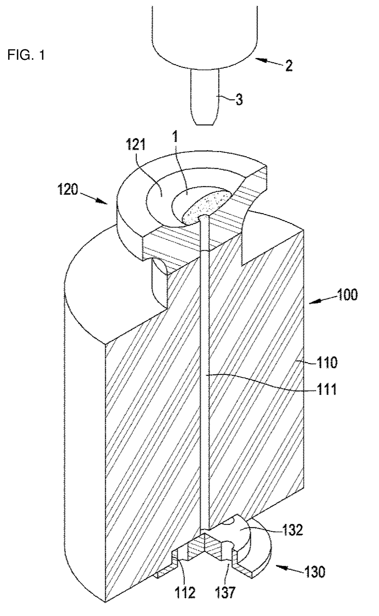
The casting method is mainly used to manufacture a specimen made of an amorphous alloy, but there is a problem in that it is necessary to rapidly cool molten metal during the manufacturing process, at a speed higher than a speed at which metal elements form crystal structures, even though the amorphous alloy has no crystal structure and thus has better physical properties such as rigidity than general metal.
Because the method of introducing the molten metal into the mold cavity by using gravity has a problem in that the molten metal cannot quickly flow into the mold cavity due to the frictional force in the narrow passageway, a method is mainly used which casts an amorphous alloy specimen by rapidly drawing the molten metal into the mold cavity by using negative pressure made by suction and by solidifying the molten metal by transferring heat to a main mold body having high thermal conductivity before crystallization of metal, and a casting mold used for the method is mainly used.
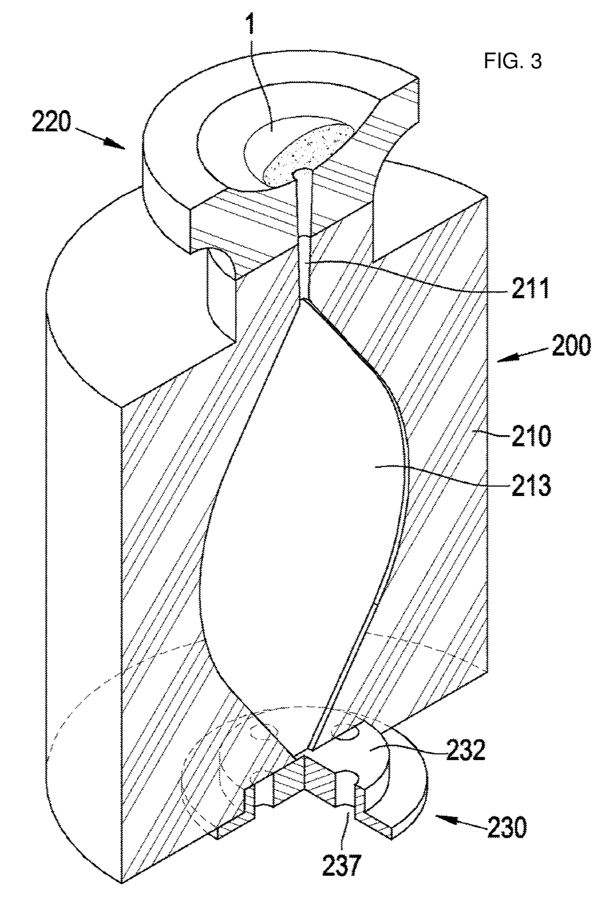
However, several problems are found as a result of casting an amorphous alloy sheet by using the casting mold 200 configured as described above.
First, it is ascertained that casting defects occur at a severe level in the casted alloy specimen because the molten metal non-uniformly flows from an upper end to a lower end of the mold cavity 213.
Therefore, it is ascertained that an appropriate amorphous metal sheet cannot be casted by using the configuration of the differential pressure type casting mold in the related art as it is.
According to the disclosure in Document 1, a small sheet made of an amorphous alloy at a specimen level is manufactured by using the apparatus and the method, but there are problems in that the manufactured sheet has a very irregular surface state such that the manufactured sheet needs to be machined to make a specimen by cutting and removing a significantly large part of a surface of a casted product, quality of the casted specimen is very irregular because the casting is not performed in a sealed mold, and as a result, it is impossible to obtain a shape required as a final product.
Further, according to the method and the apparatus according to the invention disclosed in Document 1, a driving device, which operates the support, the heater, and the chill member, is additionally required in comparison with the casting mold of the type illustrated in FIG. 1, and as a result, there are problems in that a configuration of the apparatus and a control method are very complicated and a large amount of costs is required.

Method used


Image

  • Casting mold for metal sheet
  • Casting mold for metal sheet
  • Casting mold for metal sheet

Examples


first embodiment

[0081]FIGS. 4 to 7 are views of a casting mold according to the present invention, in which FIGS. 4 and 7 are longitudinal sectional views of the casting mold, and FIGS. 5 and 6 are perspective views illustrating a lower mold and a state in which a ring is mounted in the lower mold.

[0082]FIGS. 8 and 9 are photographs of a prototype of a metal sheet casted by using the casting mold according to the first embodiment of the present invention, and a graph illustrating a result of measuring an X-ray diffraction pattern.

[0083]FIG. 10 is a perspective view of a modified example of the ring illustrated in FIG. 6.

second embodiment

[0084]FIG. 11 is a cross-sectional view of a casting mold according to the present invention.

third embodiment

[0085]FIG. 12 is a perspective view of a casting mold according to the present invention.

[0086]FIG. 13 is a longitudinal sectional view taken along line A-A in FIG. 12.

[0087]FIG. 14 is an enlarged view of part ‘B’ in FIG. 13.

[0088]FIGS. 15 to 17 are enlarged views of part ‘C’ in FIG. 13 and illustrate various modified configurations.


PUM

PropertyMeasurementUnit
arc angleaaaaaaaaaa
thermal insulatoraaaaaaaaaa
shapeaaaaaaaaaa

Abstract

The present invention relates to a casting mold for a metal sheet by drawing molten metal into a mold cavity and cooling the molten metal, and the casting mold according to the present invention includes: a support portion at an upper side on which molten metal is disposed or a solid metal is placed and melted; a mold cavity at a lower side in which the metal sheet is formed as the molten metal is drawn from the support portion while filling the mold cavity and cooled; and a passageway through which the molten metal is drawn into the mold cavity from the support portion, in which the mold cavity includes a first surface at the upper side which communicates with the passageway, and a second surface at the lower side which faces the first surface, a plurality of suction portions for drawing the molten metal are formed in the second surface and extended downward from the second surface, the suction portions are connected to a vacuum source and configured to draw the molten metal by suctioning air from the mold cavity, and a blocking member, which is in contact with the second surface or the suction portions to prevent a leakage of the molten metal and allow an air flow, is disposed on the suction portions in the mold cavity.

Description

TECHNICAL FIELD[0001]The present invention relates to a casting mold for a metal sheet, and particularly, to a casing mold configured to cast a metal sheet by drawing molten metal into a cavity of the mold and then cooling the molten metal.BACKGROUND ART[0002]Various casing molds and casting methods are used for metal casting, and as a metal casting methods for rapidly casting an metal product, that is, a metal casting method for rapidly cooling molten metal, a method is used which rapidly injects molten metal into a mold cavity by using gravity or by drawing the molten metal and transfers heat to the mold, thereby casting a solid metal product from the liquid molten metal.[0003]The casting method is mainly used to manufacture a specimen made of an amorphous alloy, but there is a problem in that it is necessary to rapidly cool molten metal during the manufacturing process, at a speed higher than a speed at which metal elements form crystal structures, even though the amorphous alloy...

Claims


Application Information

Patent Timeline
Patent Type & Authority Applications(United States)
IPC IPC(8): B22C9/06B22C9/08B22D27/15B22D11/055
CPCB22C9/061B22C9/08B22D27/15B22D11/055B22C9/12B22D18/04B22C9/06B22C9/067B22D18/06
Inventor LIM, KA RAMNA, YOUNG SANG
Owner KOREA INST OF MATERIALS SCI
Why Eureka
Try Eureka