Concentric fiber for space-division multiplexed optical communications and method of use

a technology of space-division multiplexing and optical communication, applied in the field of optical communication, can solve the problems of increasing the crosstalk between cores or modes with transmission distance, smf optical transmission systems now approaching intrinsic capacity limits, and unable to meet future capacity requirements

Active Publication Date: 2019-01-03
COMMSCOPE TECH LLC
View PDF5 Cites 5 Cited by
  • Summary
  • Abstract
  • Description
  • Claims
  • Application Information

AI Technical Summary

Benefits of technology

[0010]Another embodiment of the invention is directed to a method of communicating that includes generating a first optical signal and generating a second optical signal. The method also includes providing a concentric spatial division multiplexed (SDM) fiber having a core formed of a first material having a first relatively high refractive index material and a first high index ring formed around the core of a second material having a second relatively high refractive index, the core and the first high index ring being separated by a ring of third material having a third refractive index lower than the first relatively high refractive index and lower than the second relatively high refractive index. The first optical signal is transmitted into...

Problems solved by technology

However, current SMF optical transmission systems are now approaching their intrinsic capacity limits, and it is expected that they will be unable to meet future capacity requirements.
An important issue for MCF is that crosstalk between cores or modes increases with transmission distance, and/or arises due to bends and fiber imperfections.
Furthermore, it is difficult and expensive to manufacture optical fibers having multiple cores within a single cladding.
Furthermore, connectivity of the MCF is complicated because the multiple cores require precise rotational alignment of the fiber end about th...

Method used


Image

  • Concentric fiber for space-division multiplexed optical communications and method of use
  • Concentric fiber for space-division multiplexed optical communications and method of use
  • Concentric fiber for space-division multiplexed optical communications and method of use

Examples


Embodiment Construction

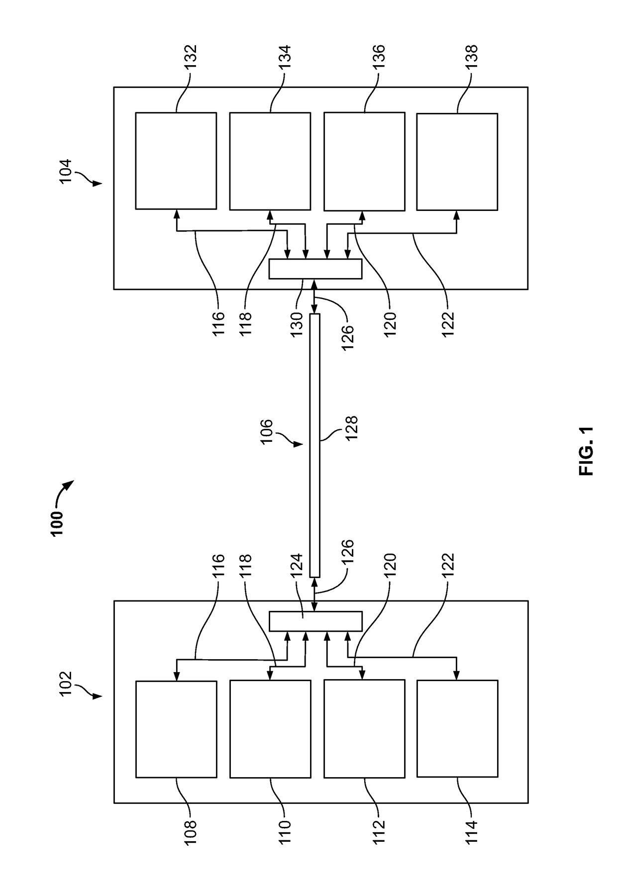
[0024]The present invention is directed to an approach to space division multiplexing (SDM) that makes use of concentric ring cores. Where the rings are separated relatively far away from each other and / or the refractive index difference between a ring and the cladding is sufficiently large, the modal electromagnetic fields are relatively strongly bound to the individual rings. The modal fields bound to a particular ring may constitute an independent transmission channel. The multitude of modal fields that may exist for a particular ring can facilitate space division multiplexing to be employed on a ring level. Since the concentric ring cores can be implemented in a circularly symmetric geometry, connectivity of such a fiber is simpler than with a multiple core fiber (MCF), which requires rotational alignment about the fiber axis to ensure that the cores are aligned with their respective mates.

[0025]In other cases, where the rings are located closer together, and / or the refractive i...


PUM


Abstract

A space-division multiplexed optical fiber includes a relatively high refractive index optical core region surrounded by alternating regions of relatively low and relative high refractive index material, forming concentric high index rings around the core. The optical core region supports propagation of light along at least a first radial mode associated with the optical core region and a high index ring region supports propagation of light along at least a second radial mode associated with the high index ring region. The second radial mode is different from the first radial mode.

Description

CROSS REFERENCE TO RELATED APPLICATION[0001]This application claims the benefit of provisional application Ser. No. 62 / 514,581, filed Jun. 2, 2017, which is incorporated herein by reference in its entirety.BACKGROUND OF THE INVENTION[0002]The present invention is generally directed to optical communications, and more specifically to improved methods of increasing the information transmission capacity for a single fiber.[0003]Historically, several steps have been taken to improve the information transmission bandwidth in single mode fiber (SMF) optical communications systems, which are typically used for transmitting information over distances of a kilometer or more. Low transmission loss silica fibers were developed in the late 1970s and early 1980s, permitting the use of silica fibers over greater distances. The advent of erbium-doped fiber amplifiers (EDFAs), providing amplification for signals around 1550 nm, permitted the transmission of signals over even greater distances, whil...

Claims


Application Information

Patent Timeline
IPC IPC(8): H04B10/25G02B6/036H04J14/02
CPCH04B10/25G02B6/03644G02B6/03688H04J14/02G02B6/02042H04B10/2581H04J14/04G02B6/36H04B10/85H04J14/0201H04Q2011/002H04Q2011/0024
Inventor CHAMBERLAIN, JOHN CHARLESFLORIS, SANDER JOHANNES
Owner COMMSCOPE TECH LLC
Why Eureka
Try Eureka