Customizable 3d-printed lighting device

a 3d printing and lighting technology, applied in the field of customizable 3d printing lighting devices, can solve the problems of limited customization of downlighters' light distribution, and achieve the effect of improving adhesion between parts and adhesion between parts

Active Publication Date: 2019-01-10
SIGNIFY HLDG BV
View PDF0 Cites 6 Cited by
  • Summary
  • Abstract
  • Description
  • Claims
  • Application Information

AI Technical Summary

Benefits of technology

The invention provides a new lighting concept that allows for the design of lighting devices that are more flexible and easier to install. The lighting devices use a reflective additive in a polymer material to produce the desired optical properties. The beam modifying element, which can reduce glare, also helps to shape the beam. The window and reflector cavity wall materials can be the same polymer material, which improves adhesion between parts. In some embodiments, the same polymer material is used for the beam modifying element and the window, which ensures consistent quality and performance. Overall, the invention allows for greater design flexibility and improved performance of lighting devices.

Problems solved by technology

A disadvantage of the current lighting systems is amongst others that currently installed downlighter luminaires (“downlighters”) have a (substantially) symmetrical light distribution (while many spaces are not symmetrical).
Further, downlighters have a light distribution which is very limitedly customizable, or even not customizable, to the specific properties of a space.

Method used


Image

  • Customizable 3d-printed lighting device
  • Customizable 3d-printed lighting device
  • Customizable 3d-printed lighting device

Examples


Embodiment Construction

[0065]3D printing of e.g. downlights offers unique design and customization opportunities. One may design almost free-form intensity profiles and create a look and feel with fits to the unique architecture of a new or refurbished building. It also offers opportunities for retrofitting existing lighting systems (i.e. systems based on TL or other conventional light source). This means that is possible to reproduce the intensity profile of a conventional luminaire exactly by a 3D printed lighting system. This invention describes a process to fabricate tailor-made lighting devices, such as downlights. The described technology and embodiments are not limited to downlights but can be applied to e.g. office lighting and high-bay lighting as well. The invention focuses on Fused Deposition Modelling (FDM) which is also called Fused Filament Fabrication (FFF).

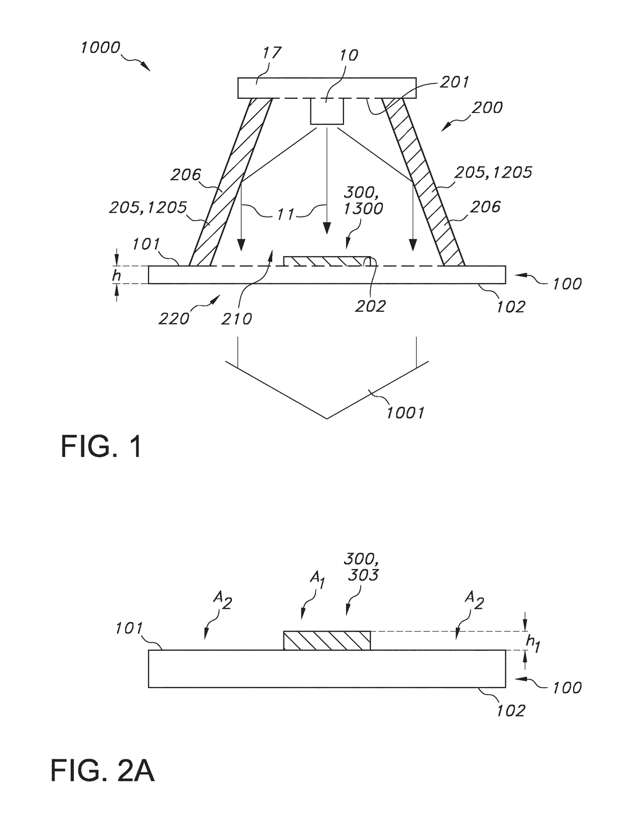
[0066]FIG. 1 schematically depicts an embodiment of a lighting device 1000 configured to provide a beam of lighting device light 1001. ...


PUM

PropertyMeasurementUnit
Symmetryaaaaaaaaaa
Luminescenceaaaaaaaaaa

Abstract

The invention provides lighting device (1000) configured to provide a beam of lighting device light (1001), the lighting device (1000) comprising: (a) a light transmissive window (100) having a first window side (101) and a second window side (102); (b) a reflector (200) comprising a reflector cavity (210), the reflector cavity (210) comprising a first reflector cavity side (201), a reflector cavity exit side (202), a reflector cavity wall (205) bridging said first reflector cavity side (201) and said reflector cavity exit side (202); wherein the reflector cavity wall (205) comprises a light reflective material (206), wherein the recavity wall (205) comprises a 3D-printed cavity wall (1205); wherein at least part of the first window side (101) is configured as reflector cavity exit window (220) at the reflector cavity exit side (202); (c) a light source (10) configured at the first reflector cavity side (201) and configured to provide light source light (11) within said reflector cavity (210); and (d) a beam modifying element (300) configured at the first window side (201) within the reflector cavity (210), wherein the beam modifying element (300) comprises a 3D-printed beam modifying element (1300).

Description

FIELD OF THE INVENTION[0001]The invention relates to a method for producing a lighting device.BACKGROUND OF THE INVENTION[0002]Fused deposition modelling (FDM) is known in the art. EP0833237 describes for instance an apparatus incorporating a movable dispensing head provided with a supply of material which solidifies at a predetermined temperature, and a base member, which are moved relative to each other along “X”, “Y,” and “Z” axes in a predetermined pattern to create three-dimensional objects by building up material discharged from the dispensing head onto the base member at a controlled rate. The apparatus is preferably computer driven in a process utilizing computer aided design (CAD) and computer-aided (CAM) software to generate drive signals for controlled movement of the dispensing head and base member as material is being dispensed. Three-dimensional objects may be produced by depositing repeated layers of solidifying material until the shape is formed. Any material, such a...

Claims


Application Information

Patent Timeline
IPC IPC(8): F21S8/02F21V3/06F21V7/24F21V9/30F21V3/04B33Y80/00B29C64/118
CPCF21S8/026F21V3/062F21V7/24F21V9/30B33Y10/00B33Y80/00B29C64/118F21Y2115/10B29L2031/747F21V3/049F21S8/04F21V7/04F21V13/14F21V3/12F21V9/40
Inventor BOONEKAMP, ERIK PAULHIKMET, RIFAT ATA MUSTAFAVAN HAL, PAULUS ALBERTUS
Owner SIGNIFY HLDG BV
Why Eureka
Try Eureka