Method and device for separating composite materials and mixtures, in particular solid-material mixtures and slags

a composite material and solid-material mixture technology, applied in grain treatment, transportation and packaging, other domestic articles, etc., can solve the problems of increasing environmental impact, increasing waste that occurs after use (end of life), and exacerbated supply of raw materials in the industry, etc., to confront our society with rapidly mounting challenges

Active Publication Date: 2019-01-24
GRAF DENIZ
View PDF1 Cites 0 Cited by
  • Summary
  • Abstract
  • Description
  • Claims
  • Application Information

AI Technical Summary

Benefits of technology

[0010]The object of the present invention was to provide an alternative method and an alternative device that allow composite materials and mixtures, in particular solid-material mixtures and

Problems solved by technology

The complex of problems of waste disposal is well known and constitutes one of the biggest challenges of our time.
In addition to waste that occurs during production of consumables and economic goods, waste that occurs after their use (end of life) in particular is also an increasing problem with global impact on the environment.
Aside from the waste problem as such, the supply of the industry with raw materials exacerbates the problem because of shortages.
The resulting feedback effects may confront our society with rapidly mounting challenges.
A strong increase in the use of composite materials also adds to the complication of recycling management.
However, disassociating these materials into their components and recycling them is very intricate.
However, this means that the contained raw materials are lost.
The reason for the common disposal practice rests in the complexity of the mixt

Method used


Image

  • Method and device for separating composite materials and mixtures, in particular solid-material mixtures and slags
  • Method and device for separating composite materials and mixtures, in particular solid-material mixtures and slags
  • Method and device for separating composite materials and mixtures, in particular solid-material mixtures and slags

Examples


Embodiment Construction

[0062]The following embodiments are examples and are not intended to limit the invention in any way.

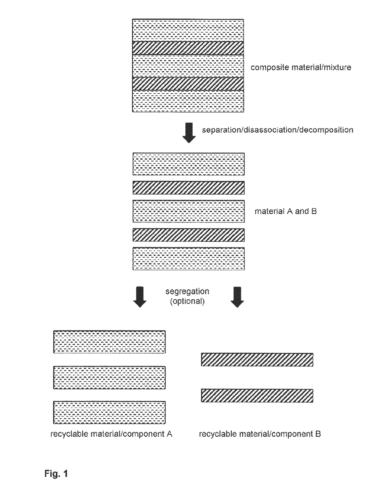
[0063]FIG. 1 schematically shows the different steps of one embodiment of the method according to the invention. First, the bond at the contact surfaces of the different materials of the composite material or of the mixture is severed (i.e. broken up or decomposed) and then the different materials can optionally be segregated from each other so as to recover the homogenous recyclable material (i.e. the original components of the composite material / mixture).

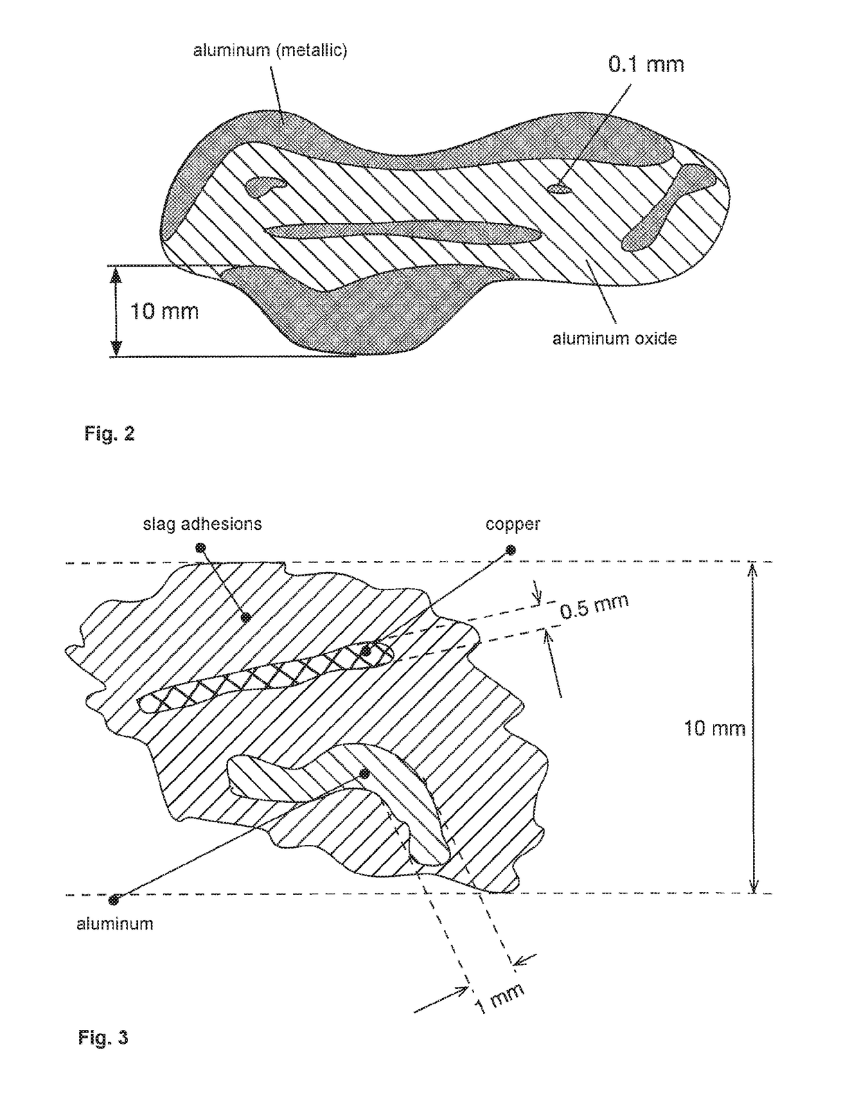
[0064]FIG. 2 shows a possible structure of the waste products slag and aluminum dross that occur both in primary processing and in subsequent processing of metals, in particular aluminum. During a reduction process, in which aluminum oxides are processed into metallic aluminum, for example, a layer consisting of metallic aluminum and aluminum oxides forms on the surface of the aluminum prior to its casting. This layer is a result of...


PUM

PropertyMeasurementUnit
Angleaaaaaaaaaa
Angleaaaaaaaaaa
Angleaaaaaaaaaa

Abstract

A method for separating composite materials and mixtures, in particular solid-material mixtures and slags, and to a device for carrying out said method. The method for separating composite materials and mixtures comprises the step of transporting the composite material or the mixture through a separating device. The composite material to be separated or the mixture to be separated is excited by mechanical impulses as it passes through the separating device and is thereby separated. The device (1) for carrying out the method comprises a drive unit (21) for driving a rotor element (32), which is connected to a bearing/shaft unit (22) and which is part of a rotor unit (31). The rotor element itself has at least one rotor tool (33) and each rotor tool has at least one rotor tool component (34) and is surrounded by a stator element (42), which is part of a stator unit (41). The stator element itself has at least one stator tool (43) and each stator tool has at least one stator tool component (44). The rotor element and the stator element are substantially cylindrical.

Description

BACKGROUND OF THE INVENTION[0001]The present invention relates to a method and to a device for disassociating, i.e. decomposing, and segregating composite materials and mixtures, in particular solid-material mixtures and slags.[0002]It is to be noted that, in this context, the terms disassociating, separating and decomposing mean that the different materials that are part of the composite material or of the mixture are detached from each other, i.e. that a separation along the contact surface is effected. Consequently, decomposing does not describe a classic chemical digestion (e.g. in acid) in this case, but instead exactly the described detachment of the different materials (e.g. wood, metal, plastic, etc.) in the composite material or in the mixture from each other. While the materials are subsequently no longer connected to each other, they are not yet separated spatially. A spatial separation of the materials is achieved by segregation. Subsequent to segregation, which describe...

Claims


Application Information

Patent Timeline
IPC IPC(8): B09B3/00B03B9/04B03B9/06B29B17/02
CPCB09B3/0016B03B9/04B03B9/061B29B17/0206B29B2017/0492B29L2030/00B29L2031/3425B29L2031/3462B29L2031/7164B29B2017/0227B29B2017/0268B29L2009/003B02C13/1807B02C13/185B09B3/00B09B5/00B29B17/02B02C2013/145B29B2017/0217B29L2009/00Y02W30/52Y02W30/62B09B2101/30B09B3/80B02C23/18B02C18/18B02C23/24B02C2018/188
Inventor GRAF, DENIZ
Owner GRAF DENIZ
Why Eureka
Try Eureka