Wheel blank positioning end face correction device

a technology of positioning end face and correction device, which is applied in the direction of grinding drive, grinding feeder, manufacturing tools, etc., can solve the problem of very low precision of clamping positioning, and achieve the effect of improving production efficiency, flexible structure, and improving precision of correction

Active Publication Date: 2019-01-24
CITIC DICASTAL
View PDF0 Cites 8 Cited by
  • Summary
  • Abstract
  • Description
  • Claims
  • Application Information

AI Technical Summary

Benefits of technology

[0012]By adopting closed-loop control of first measurement and then correction, the precision of correction is greatly improved; by setting double stations, deformation of next blank to be corrected is measured while one blank is corrected, so that the production efficiency is greatly improved; and the device is flexible in structure, stable, efficient and advanced in process.

Problems solved by technology

When the wheel blank positioning end face is deformed greatly, the clamping positioning precision is very low, and some positions of the inner rim, outer rim or flange of the machined wheel cannot be turned, thus directly resulting in a reject.

Method used


Image

  • Wheel blank positioning end face correction device
  • Wheel blank positioning end face correction device
  • Wheel blank positioning end face correction device

Examples


Embodiment Construction

[0017]Details and working conditions of a specific device provided by the present application will be given below in combination with the accompanying drawings.

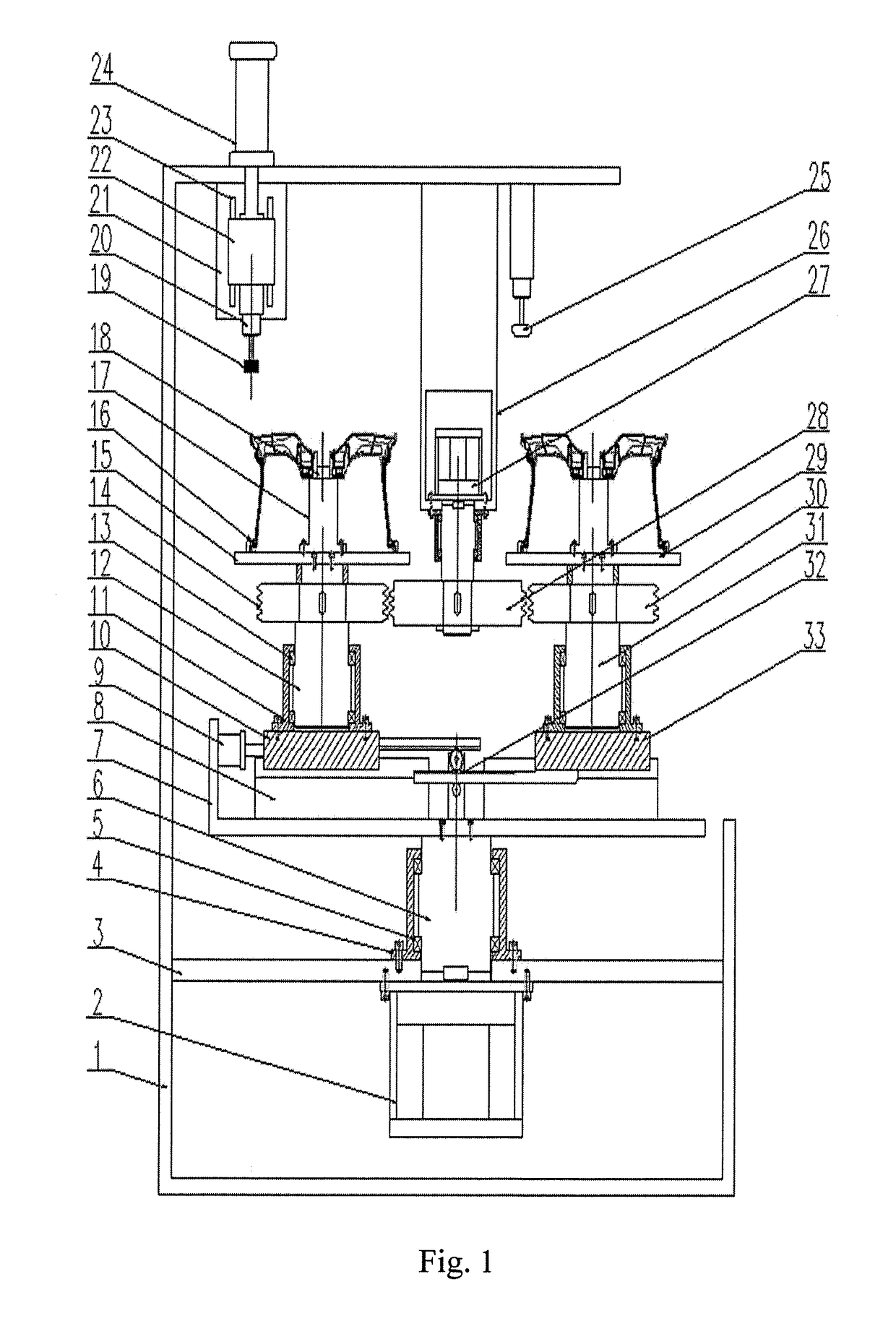
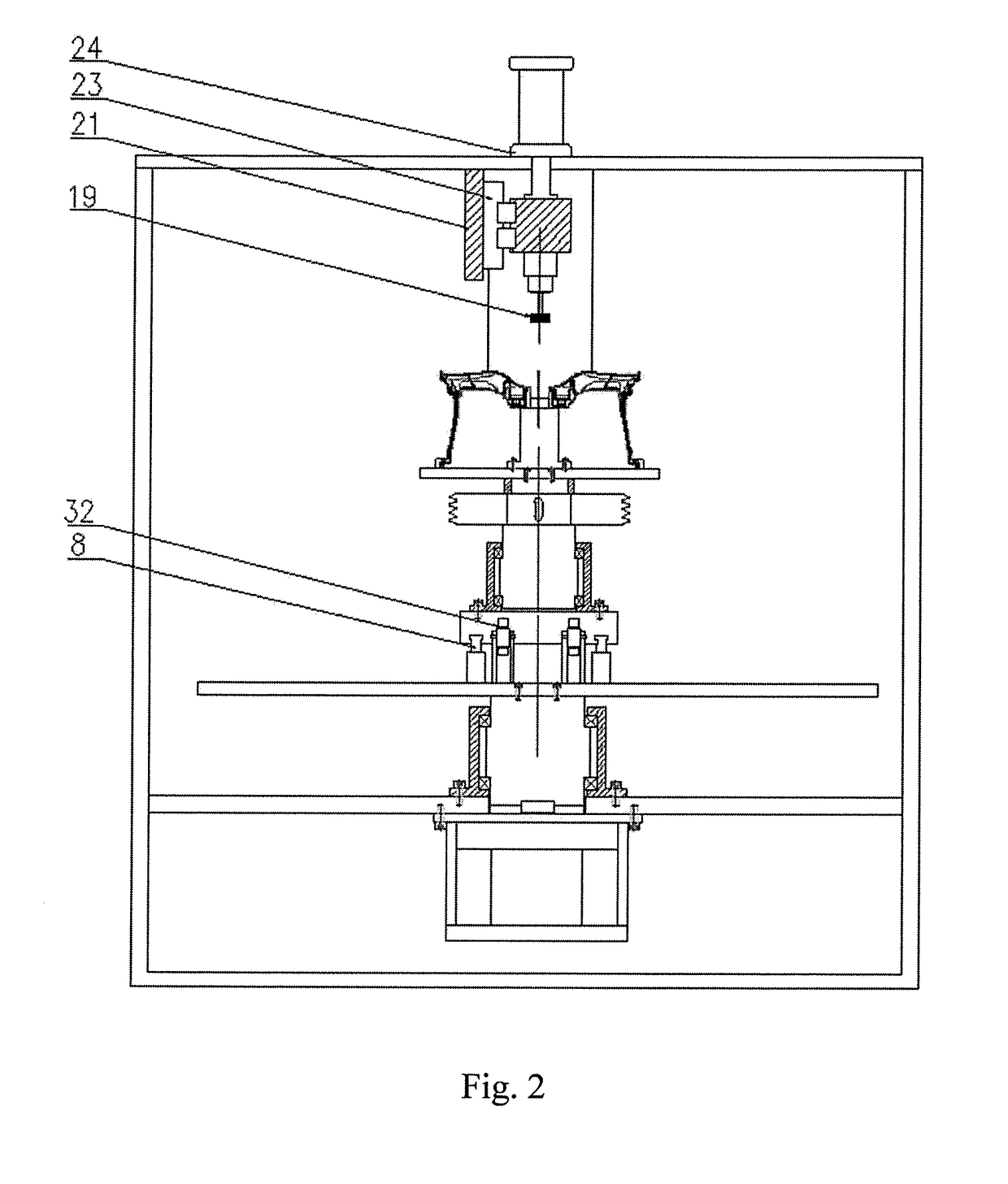
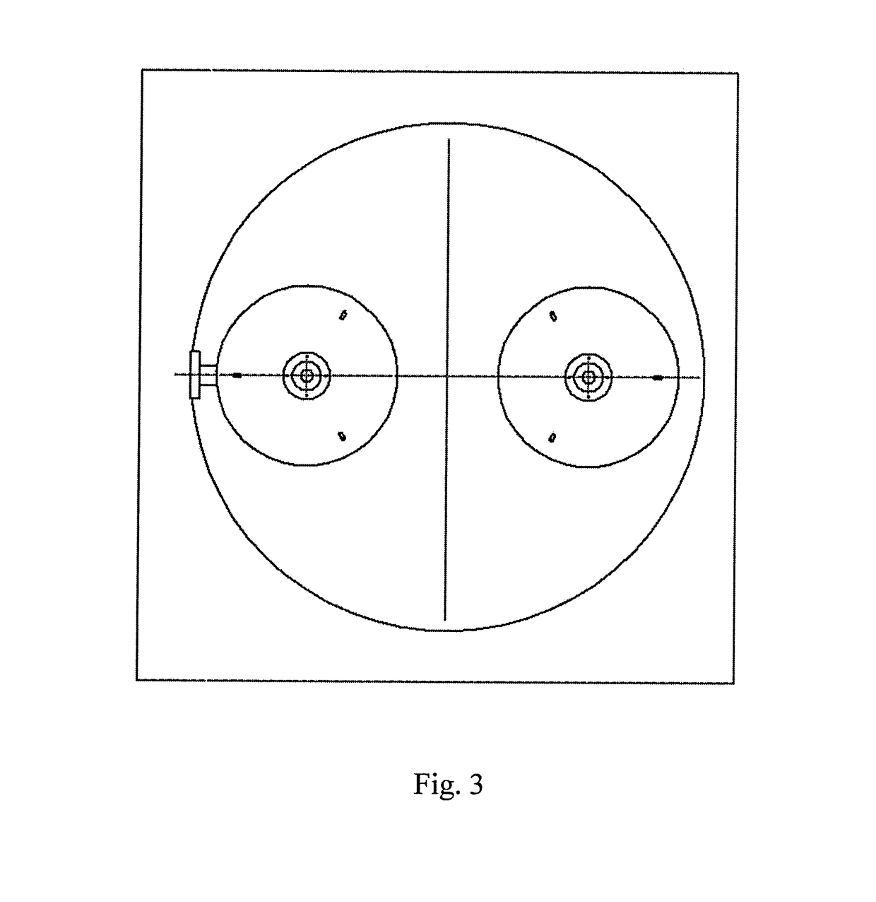
[0018]A wheel blank positioning end face correction device comprises a frame 1, a servo motor I 2, a support frame 3, bearing seats 4, bearings 5, a shaft 6, a rotating platform 7, a guide rail 8, a cylinder 9, a left slide plate 10, a left bearing seat 11, a left shaft 12, a left bearing 13, a left driven grooved friction wheel 14, a left workbench 15, corner cylinder pressure claws 16, mandrel seats 17, mandrels 18, a grinding wheel 19, a grinding wheel drive motor 20, a support plate 21, a feeding slide plate 22, feeding guide rails 23, a linear motor 24, a distance measuring sensor 25, a fixed plate 26, a servo motor II 27, a driving grooved friction wheel 28, a right workbench 29, a right driven grooved friction wheel 30, a right shaft 31, a gear rack structure 32 and a right slide plate 33.

[0019]The servo motor I 2 is f...


PUM


Abstract

The present application disclose a wheel blank positioning end face correction device, comprising a frame, a servo motor I, a support frame, a bearing seat, a bearing, a shaft, a rotating platform, a guide rail, a cylinder, a left slide plate, a left bearing seat, a left shaft, a left bearing, a left driven grooved friction wheel, a left workbench, corner cylinder pressure claws, mandrel seats, mandrels, a grinding wheel, a grinding wheel drive motor, a support plate, a feeding slide plate, feeding guide rails, a linear motor, a distance measuring sensor, a fixed plate, a servo motor II, a driving grooved friction wheel, a right workbench, a right driven grooved friction wheel, a right shaft, a gear rack structure and a right slide plate.

Description

CROSS-REFERENCE TO RELATED APPLICATIONS[0001]This application claims priority to Chinese Patent Application No. 201710598360.X, filed on Jul. 21, 2017, which is hereby incorporated by reference in its entirety.TECHNICAL FIELD[0002]The present application relates to the technical field of deformation correction, specifically to a correction device for a wheel blank machining positioning end face.BACKGROUND ART[0003]Casting deformation often occurs in the aluminum alloy wheel cast molding process, and the front end face of a blank is used for axial positioning of machining, so the deformation of the wheel blank positioning end face directly determines the positioning precision. When the wheel blank positioning end face is deformed greatly, the clamping positioning precision is very low, and some positions of the inner rim, outer rim or flange of the machined wheel cannot be turned, thus directly resulting in a reject.SUMMARY OF THE INVENTION[0004]The present application is aimed at pr...

Claims


Application Information

Patent Timeline
Patent Type & Authority Applications(United States)
IPC IPC(8): B24B49/12B24B9/04B24B29/00
CPCB24B49/12B24B9/04B24B29/005B24B7/16B24B27/0023B24B41/005B24B41/02B24B41/06B24B47/20B24B49/00B24B55/00B24B5/44B24B47/22
Inventor LIU, HUIYINGLIU, WEIDONGXUE, BOWEN
Owner CITIC DICASTAL
Why Eureka
Try Eureka