Precisely controlled chirped diode laser and coherent lidar system

a laser and diode technology, applied in lasers, laser details, instruments, etc., can solve the problems of sensitive detectors having difficulty dealing with crosstalk from other lidar systems or other sources of light, and the lidar system suffers from major challenges and limitations

Active Publication Date: 2019-01-24
INTEL CORP
View PDF0 Cites 39 Cited by
  • Summary
  • Abstract
  • Description
  • Claims
  • Application Information

AI Technical Summary

Problems solved by technology

TOF LIDAR suffers from some major challenges and limitations.
Further, these very sensitive detectors often have difficulty dealing with crosstalk from other LIDAR systems or from other sources of light (including direct sunlight) when operated in real-world situations.

Method used


Image

  • Precisely controlled chirped diode laser and coherent lidar system
  • Precisely controlled chirped diode laser and coherent lidar system
  • Precisely controlled chirped diode laser and coherent lidar system

Examples


Embodiment Construction

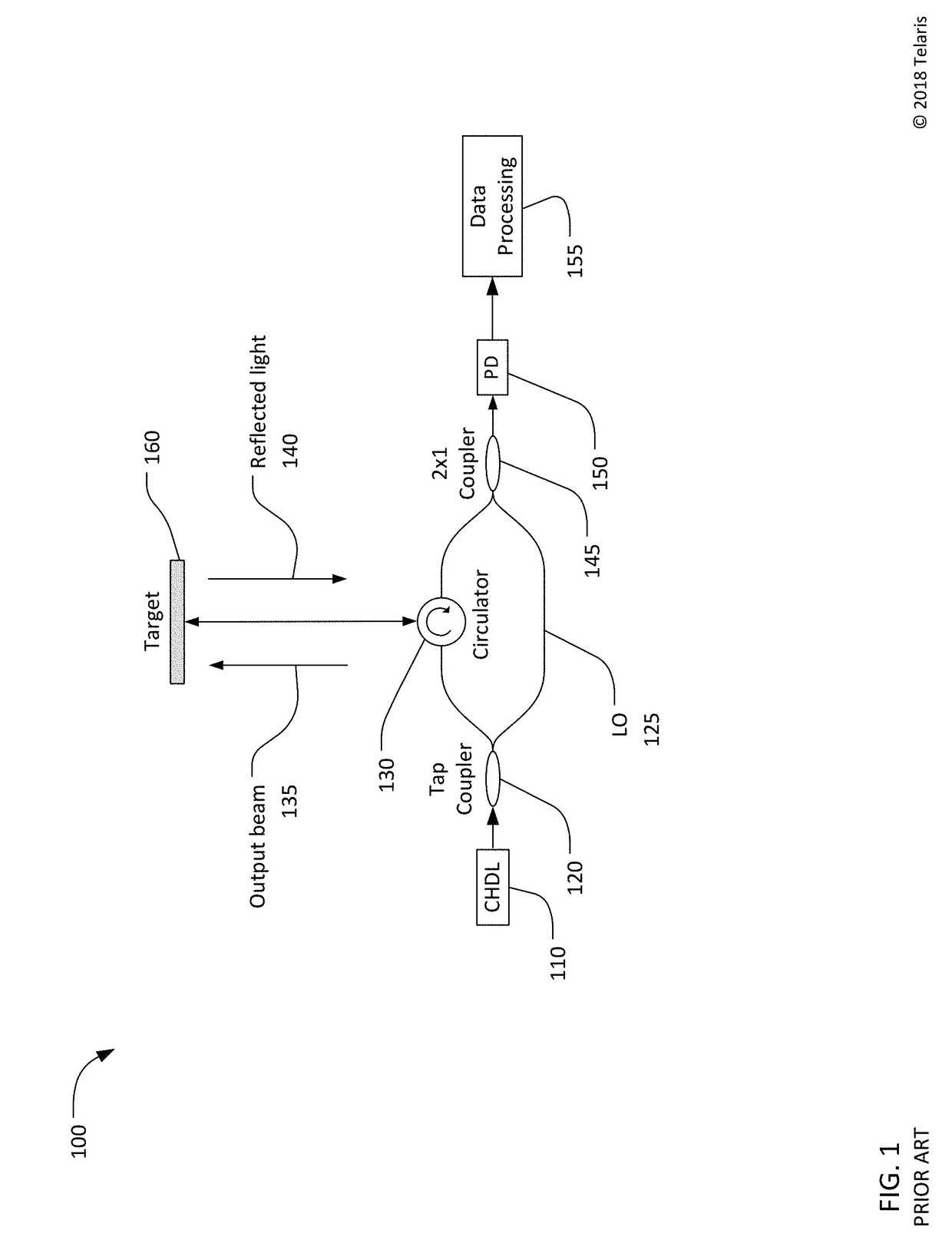
[0049]Description of Apparatus

[0050]The key requirement for a coherent chirped LIDAR system is a laser whose optical frequency varies with time in a precisely controlled fashion. LIDAR systems commonly incorporate semiconductor diode lasers and attempt to control the laser to produce a precisely linear chirped wave. However, the principles described in this patent can be more generally applied to any type of laser whose output frequency can be varied by changing one or more input parameters. These principles can also be applied to generating nonlinear chirps.

[0051]Feedback-controlled chirped diode lasers measure the frequency output characteristic of the laser and use the measurement to provide closed-loop feedback to control the laser output frequency. However, measuring and controlling the rate of change of the laser output frequency typically requires a finite time interval. For example, a fraction of the laser output power may be transmitted through an unbalanced (or asymmetric)...


PUM

PropertyMeasurementUnit
optical frequencyaaaaaaaaaa
periodic frequency versus time functionaaaaaaaaaa
timeaaaaaaaaaa

Abstract

Frequency modulated lasers, LIDAR systems, and methods of controlling laser are disclosed. A laser source emits an optical beam having an optical frequency that changes in response to a signal applied to an input of the laser source. A laser driver that generates the signal applied to the input to cause the optical frequency to vary in accordance with a periodic frequency versus time function. The laser driver generates the signal for a current period of the periodic frequency versus time function based, at least in part, on optical frequency versus time measurements of one or more prior periods of the periodic frequency versus time function.

Description

NOTICE OF COPYRIGHTS AND TRADE DRESS[0001]A portion of the disclosure of this patent document contains material which is subject to copyright protection. This patent document may show and / or describe matter which is or may become trade dress of the owner. The copyright and trade dress owner has no objection to the facsimile reproduction by anyone of the patent disclosure as it appears in the Patent and Trademark Office patent files or records, but otherwise reserves all copyright and trade dress rights whatsoever.RELATED APPLICATION INFORMATION[0002]This patent claims priority from provisional patent application No. 62 / 675,567, filed May 23, 2018, titled HIGH-SPEED COHERENT LIDAR, and provisional patent application No. 62 / 536,425, filed Jul. 24, 2017, titled COHERENT CHIRPED LIDAR FOR 3D IMAGING, the contents of both are incorporated by reference herein in their entirety.BACKGROUNDField[0003]This disclosure relates to three-dimensional (3D) image systems and, specifically, to cohere...

Claims


Application Information

Patent Timeline
Patent Type & Authority Applications(United States)
IPC IPC(8): G01S17/89G01S7/481G01S7/491G02F1/21H01S5/026G01S7/4911G01S7/4914G01S7/4915G01S17/34
CPCG01S17/89G01S7/4817G01S7/4818G01S7/4914G01S7/4915G02F1/21H01S5/0261G02F2001/212G01S17/42G01S7/4812G01S7/497G01S7/4911H01S5/0064H01S5/0265H01S5/1014H01S5/5027H01S5/1212G01S17/34G02F1/212
Inventor SATYAN, NARESHRAKULJIC, GEORGE
Owner INTEL CORP
Why Eureka
Try Eureka