Chemical vapor deposition system

Inactive Publication Date: 2019-01-31
HERMES EPITEK
View PDF6 Cites 0 Cited by
  • Summary
  • Abstract
  • Description
  • Claims
  • Application Information

AI Technical Summary

Benefits of technology

The patent text is discussing the need for a wafer holder in a chemical vapor deposition system to improve the yield of the deposition process. The text describes the drawbacks of current designs which result in a high percentage of the deposition being ineffective. The technical effect of the invention is to reduce the ineffective region of deposition, resulting in a higher yield of the desired material.

Problems solved by technology

This portion can be called “an ineffective region,” resulting in a reduced yield.

Method used


Image

  • Chemical vapor deposition system
  • Chemical vapor deposition system
  • Chemical vapor deposition system

Examples


Embodiment Construction

[0037]Reference will now be made in detail to those specific embodiments of the invention. Examples of these embodiments are illustrated in accompanying drawings. While the invention will be described in conjunction with these specific embodiments, it will be understood that it is not intended to limit the invention to these embodiments. On the contrary, it is intended to cover alternatives, modifications, and equivalents as may be included within the spirit and scope of the invention as defined by the appended claims. In the following description, numerous specific details are set forth in order to provide a thorough understanding of the present invention. The present invention may be practiced without some or all of these specific details. In other instances, well-known process operations and components are not described in detail in order not to unnecessarily obscure the present invention. While drawings are illustrated in detail, it is appreciated that the quantity of the disclo...


PUM

PropertyMeasurementUnit
Angleaaaaaaaaaa

Abstract

In accordance with an embodiment, a chemical vapor deposition system is provided with a susceptor, a plurality of wafer holders, and a processing gas. The susceptor carries the plurality of wafer holders with each bearing a wafer. The susceptor makes revolution around a central axis. The periphery of the wafer includes a chamfer, and each wafer holder includes a protrudent structure having a horizontal bottom surface and an inclined bearing surface to bear the chamfer of the wafer. The processing gas approaches a surface of the wafer and is heated to form a thin film to be deposited on the surface.

Description

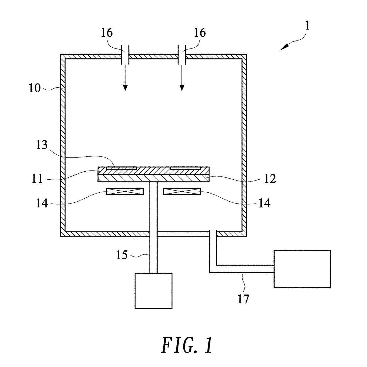
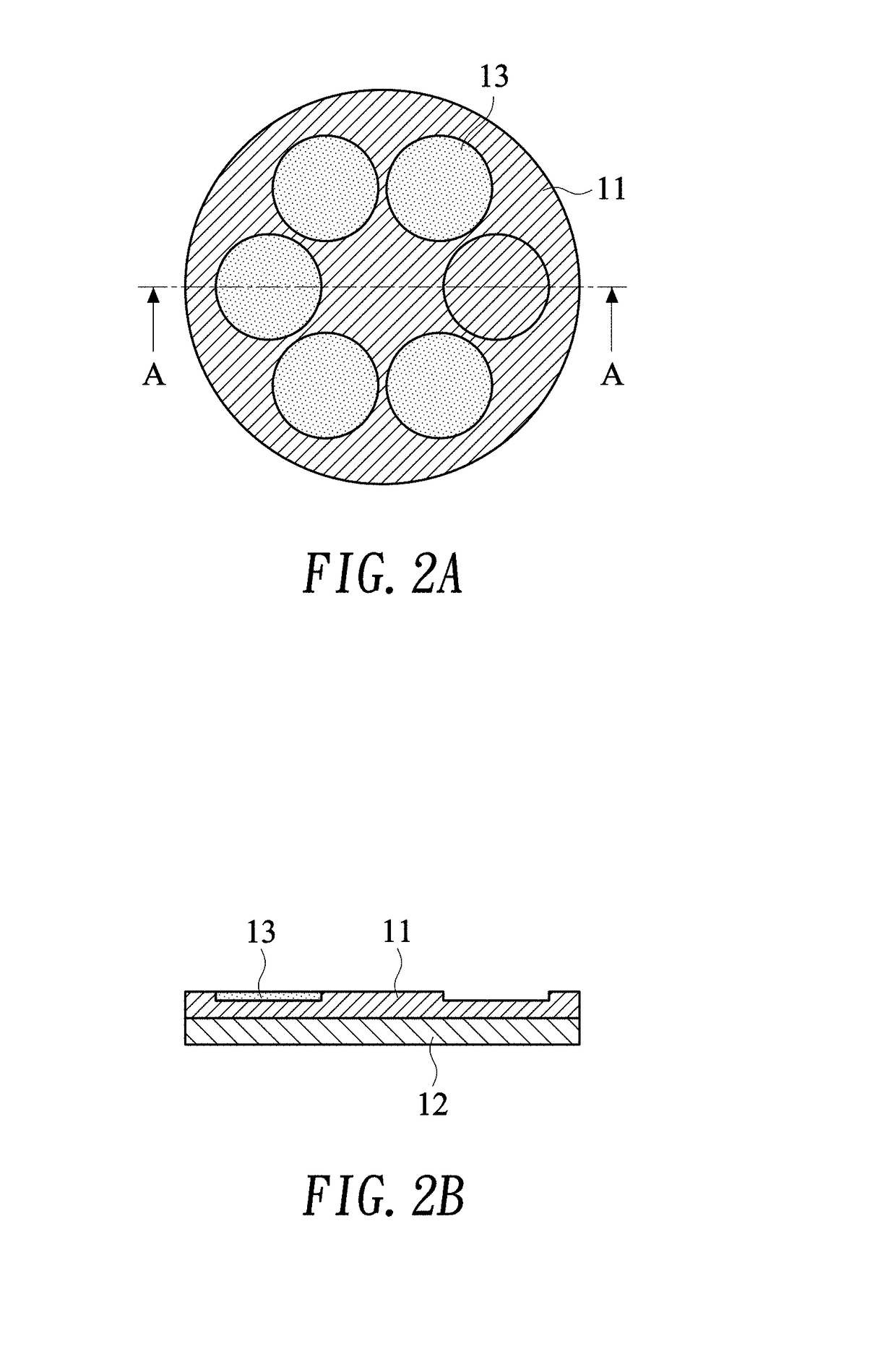
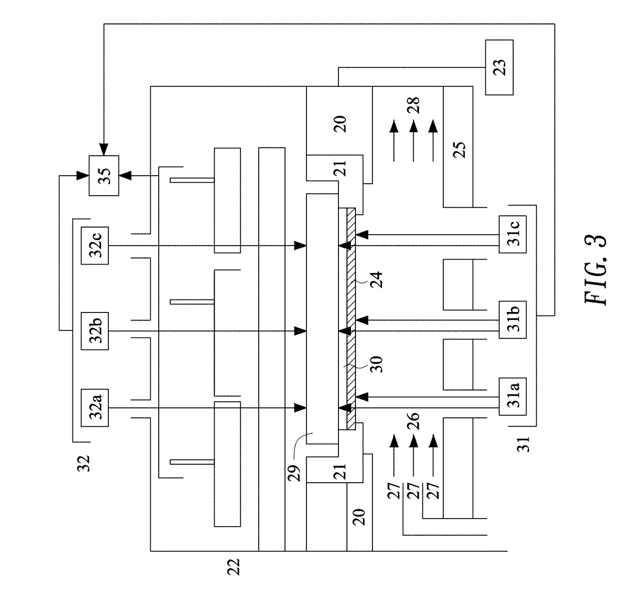
CROSS-REFERENCE TO RELATED APPLICATIONS[0001]The entire contents of Taiwan Patent Application No. 106125500, filed on Jul. 28, 2017, from which this application claims priority, are expressly incorporated herein by reference.BACKGROUND OF THE INVENTION1. Field of the Invention[0002]The present invention relates to a deposition system and more particularly relates to a gas vapor deposition system.2. Description of Related Art[0003]Metal-Organic Chemical Vapor Deposition (MOCVD) is a process to deposit a film on the surface of semiconductor wafer or other substrates. MOCVD employs a carrier gas to carry gaseous reactants or precursors into a reactor chamber loaded with wafers. A susceptor bears the wafers and uses a heating mechanism to heat the wafers as the gases approaches the substrates. As the temperature of the approaching gases is raised, one or more chemical reactions are triggered. The chemical reactions convert gaseous reactants into solid products to be deposited on the sur...

Claims


Application Information

Patent Timeline
IPC IPC(8): C30B25/10C23C16/458C23C16/46H01L21/67H01L21/687
CPCC30B25/10C23C16/4583C23C16/46H01L21/67248H01L21/68771C23C16/4584H01L21/68735H01L21/6875H01L21/68764C23C16/4585C30B25/12
Inventor LU, PO-CHINGHUANG, KUAN-NING
Owner HERMES EPITEK
Why Eureka
Try Eureka