
Depth field imaging apparatus, methods, and applications

a depth field imaging and depth field technology, applied in the field of image sensing, can solve the problems of single frequency tof suffering from limitations, phase wrapping ambiguity and multipath interference, and limiting their robustness and flexibility

Active Publication Date: 2019-01-31
CORNELL UNIVERSITY
View PDF5 Cites 15 Cited by
  • Summary
  • Abstract
  • Description
  • Claims
  • Application Information

AI Technical Summary

Benefits of technology

The invention is a depth field imaging apparatus that can simultaneously capture a light field image and a time-of-flight image using a single on-chip architecture. The apparatus includes a light field imaging component and a time-of-flight imaging component, which are both disposed over a photogate. The apparatus can be used in a depth field imaging system that includes a lens and a global shutter. The invention also includes a depth field pixel structure and an imaging method that involves acquiring a light field image and a time-of-flight image simultaneously and processing them to form a depth field image. The technical effects of the invention include improved depth of field imaging and reduced latency in image processing.

Problems solved by technology

However depth cameras typically support only one depth sensing technology at a time, which limits their robustness and flexibility.
While yielding high resolution depth maps, single frequency TOF suffers from limitations including phase wrapping ambiguity and multipath interference caused by translucent objects and scattering media.
While conceptually similar to depth fields by acquiring per-pixel values of depth and intensity, these fusion methods do not systematically control the spatio-angular sampling or transcend the traditional capture tradeoffs between aperture and depth of field for depth imaging.
Each modality has its relative disadvantages: depth from light fields require textured surfaces and is dependent on object distance for disparity, and single frequency TOF imaging suffers from phase wrapping and is limited to small aperture cameras with low shutter speeds.

Method used


Image

  • Depth field imaging apparatus, methods, and applications
  • Depth field imaging apparatus, methods, and applications
  • Depth field imaging apparatus, methods, and applications

Examples


Embodiment Construction

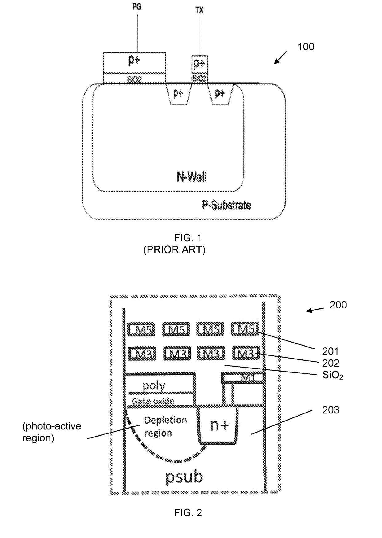
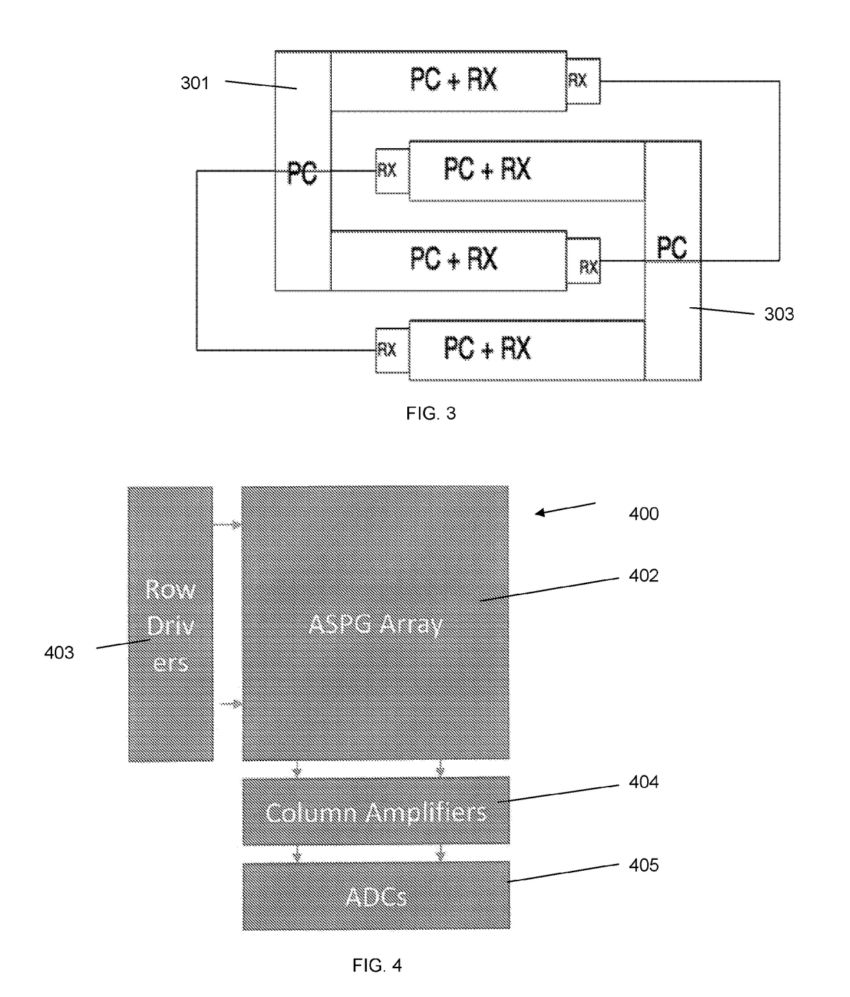
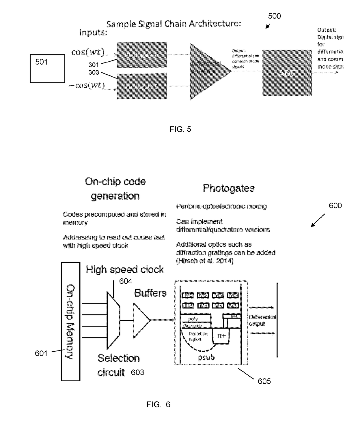
[0032]Aspects of the invention include an integrated hybrid imaging system comprising a light field (LF) imaging component and a time-of-flight (TOF) imaging component, advantageously in CMOS architecture, a LF / TOF pixel structure referred to herein as an Angle Sensitive Photogate (ASPG), and a method for simultaneously acquiring LF and TOF images with a single, integrated device. Both LF and TOF imaging component / systems are known in the art and neither of these components per se form inventive aspects of the embodied invention.

[0033]Patented LF imaging systems and methods utilizing angle sensitive pixels (ASPs), co-invented and owned by applicant are referenced above. These LF image sensors / methods utilized diffraction gratings disposed above photodiodes. A photodiode is typically a junction capacitance caused by the interface of n / p silicon. The n-doped region is held at a high voltage relative to the p-silicon, causing the area to become photoactive and generate current proporti...


PUM


Abstract

A depth of field imaging apparatus includes a light field imager and a time of flight imager combined in a single on-chip architecture. This hybrid device enables simultaneous capture of a light field image and a time of flight image of an object scene. Algorithms are described, which enable the simultaneous acquisition of light field images and a time of flight images. Associated hybrid pixel structures, device arrays (hybrid imaging systems), and device applications are disclosed.

Description

RELATED APPLICATION DATA[0001]The instant application claims priority to U.S. provisional application No. 62 / 134122 filed Mar. 17, 2015, the subject matter of which is incorporated by reference in its entirety.BACKGROUND OF THE INVENTIONField of the Invention[0002]Aspects and embodiments of the invention are generally in the field of image sensing. More particularly, aspects and embodiments relate to depth field imaging apparatus, components, methods, and applications thereof.Description of Related Art[0003]The introduction of depth sensing to capture 3D information has led to its ubiquitous use in imaging and camera systems, and has been a major focus of research in computer vision and graphics. Depth values enable easier scene understanding and modeling which in turn can realize new computer vision systems and human-computer interaction. Many methods have been proposed to capture depth information such as stereo, photometric stereo, structured illumination, light field (LF), RGB-D...

Claims


Application Information

Patent Timeline
IPC IPC(8): G01S17/02G01S17/89G01S7/481H04N13/00H04N5/374H04N13/02G01S7/4914G01S17/86G01S17/894
CPCH04N13/106H04N13/254G01S17/023G01S7/4814G01S7/4816H04N2213/001H04N5/374G01S17/89G01S17/46G01S7/4914G01S17/86G01S17/894H04N25/76
Inventor MOLNAR, ALYOSHAJAYASURIYA, SURENSIVARAMAKRISHNAN, SRIRAM
Owner CORNELL UNIVERSITY
Learn More