Electrical steel sheet and method for manufacturing the same

Active Publication Date: 2019-01-31
POHANG IRON & STEEL CO LTD
View PDF0 Cites 2 Cited by
  • Summary
  • Abstract
  • Description
  • Claims
  • Application Information

AI Technical Summary

Benefits of technology

The present invention allows for a reduction in magnetic domain size by using a laser to create a groove on the surface of an electrical steel sheet. This reduces the size of the magnetic domain, leading to improved performance. The process involves melting the steel sheet and allowing it to solidify with a tension effect caused by a continuous wave laser beam. This results in a smaller magnetic domain size and better performance.

Problems solved by technology

According to the etching method, since a groove is formed on the surface of the steel sheet by an electro-chemical corrosion reaction, it is difficult to control a groove shape (a groove width or a groove depth).
Further, since the groove is formed in an intermediate process (before a decarburization annealing process or a high-temperature annealing process) for producing the steel sheet, it may be difficult to guarantee an iron loss characteristic of a final product.
Furthermore, since an acid solution is used, the etching method may not be environmentally friendly.
However, according to the method for permanently miniaturizing a magnetic domain using a roll, stability and reliability of a mechanical processing may be unfavorable, and a process may be complicated.
According to the method for permanently miniaturizing a magnetic domain using a pulse laser, since the groove is formed by deposition, it is difficult to suppress a melted portion from being formed, so that it may be difficult to secure the iron loss improvement rate before the annealing process (the stress relief annealing (SRA) process).
Further, only a simple magnetic domain miniaturizing effect due to the groove is maintained after the annealing process, and it may be difficult to transfer the steel sheet at a high speed.

Method used


Image

  • Electrical steel sheet and method for manufacturing the same
  • Electrical steel sheet and method for manufacturing the same
  • Electrical steel sheet and method for manufacturing the same

Examples


Embodiment Construction

[0045]Merits and characteristics of the present invention, and methods for accomplishing them, will become more apparent from the following exemplary embodiments taken in conjunction with the accompanying drawings. However, the present invention is not limited to the disclosed exemplary embodiments, and may be implemented in various manners. The embodiments are provided to complete the disclosure of the present invention and to allow those having ordinary skill in the art to understand the scope of the present invention. The present invention is defined by the appended claims. Throughout the specification, the same constituent elements will be assigned the same reference numerals.

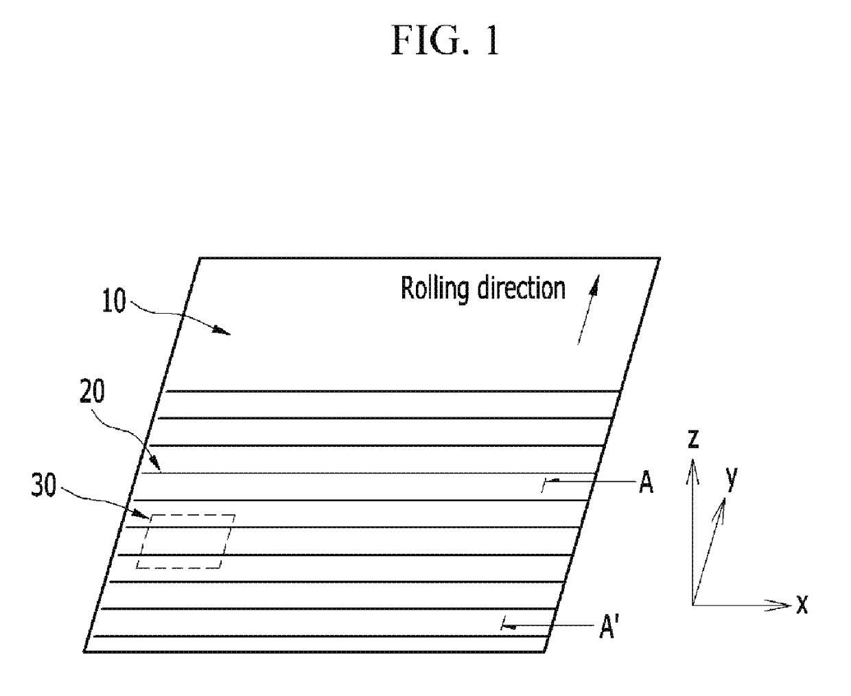
[0046]Hereinafter, an electrical steel sheet in which a groove is formed on a surface of a steel sheet in order to miniaturize a magnetic domain according to preferred exemplary embodiments of the present invention will be described.

[0047]FIG. 1 is a diagram illustrating irradiation of rays 20 of a laser th...


PUM

PropertyMeasurementUnit
Fractionaaaaaaaaaa
Poweraaaaaaaaaa
Widthaaaaaaaaaa

Abstract

Provided is an electrical steel sheet comprising: a groove formed in a surface of a steel sheet, wherein the groove includes a bottom surface, a first side surface extending from the bottom surface, and a second side surface extending from the bottom surface in opposite to the first side surface, wherein the groove has a depth from the surface to the bottom surface, a width in a rolling direction of the steel sheet, and a length in a width direction of the steel sheet, and wherein the groove is formed through laser-irradiation and removal of melt produced by the laser-irradiation; an opening defined by the bottom surface, the first side surface and the second side surface; and a first solidification portion formed on the first side surface of the groove. The first solidification portion is formed by a solidification of part of the melt produced from the laser-irradiation.

Description

TECHNICAL FIELD[0001]The present invention relates to an electrical steel sheet, and more particularly, to a grain-oriented electrical steel sheet in which a magnetic domain of the steel sheet is miniaturized by forming a groove on a surface of the steel sheet by laser irradiation.BACKGROUND ART[0002]A grain-oriented electrical steel sheet is used as an iron core material of an electrical device such as a transformer, and in order to reduce a power loss of the electrical device and to improve efficiency thereof, it is necessary to provide a steel sheet having a magnetic characteristic of less iron loss and a high magnetic flux density.[0003]In general, the grain-oriented electrical steel sheet refers to a material having texture (referred to as a “GOSS texture”) oriented in a rolling direction through a hot rolling process, a cold rolling process, and an annealing process.[0004]As a degree oriented in a direction in which iron is easily magnetized is high, the grain-oriented electri...

Claims


Application Information

Patent Timeline
IPC IPC(8): H01F1/16C21D8/12
CPCH01F1/16C21D8/1294
Inventor KWON, OH-YEOULLEE, WON-GULHAN, CHAN-HEEPARK, HYUN-CHUL
Owner POHANG IRON & STEEL CO LTD
Why Eureka
Try Eureka