Battery system and electrically driven vehicle equipped with battery system

Active Publication Date: 2019-02-07
SANYO ELECTRIC CO LTD
View PDF3 Cites 6 Cited by
  • Summary
  • Abstract
  • Description
  • Claims
  • Application Information

AI Technical Summary

Benefits of technology

[0007]A battery system of one aspect of the present invention includes: a series unit (20) in which a plurality of battery units (2) are connected in series; a heat exchanger (3) coupled with at least one of the battery units (2) in a thermal-coupling state and internally circulating a coolant; and an outer case (9) housing the series unit and the heat exchanger. Each of the battery units (2) has a plus output terminal (15A) and a minus output terminal (15B) at both ends of each of the battery units (2), and includes a plurality of battery cells stacked from the plus output terminal (15A) to the minus output terminal (15B). One of the battery units (2) disposed at an end of the plus output terminal (15A) side of the series unit (20), is disposed at an inclined posture where the end (25) of the plus output terminal (15A) side is away from a base plate (9A) of the outer case (9). Another of the battery units (2) disposed at an end of the minus output terminal side of the series unit, is disposed at an inclined

Problems solved by technology

Then, the problem may happen, that an ignition occurs inside the batt

Method used


Image

  • Battery system and electrically driven vehicle equipped with battery system
  • Battery system and electrically driven vehicle equipped with battery system
  • Battery system and electrically driven vehicle equipped with battery system

Examples


embodiment 1

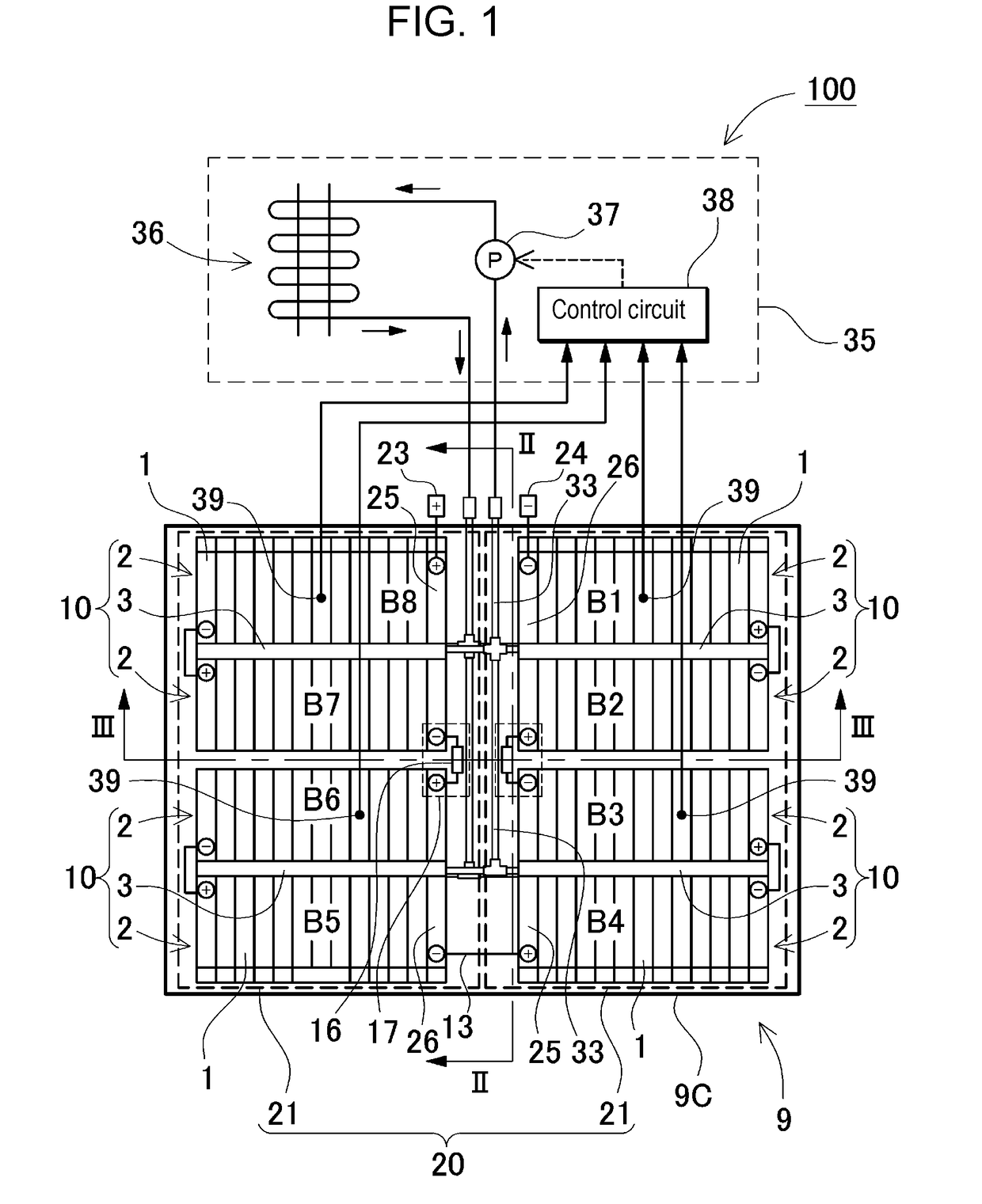
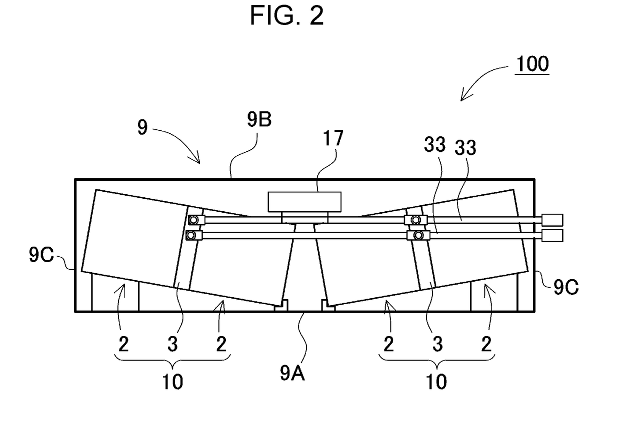
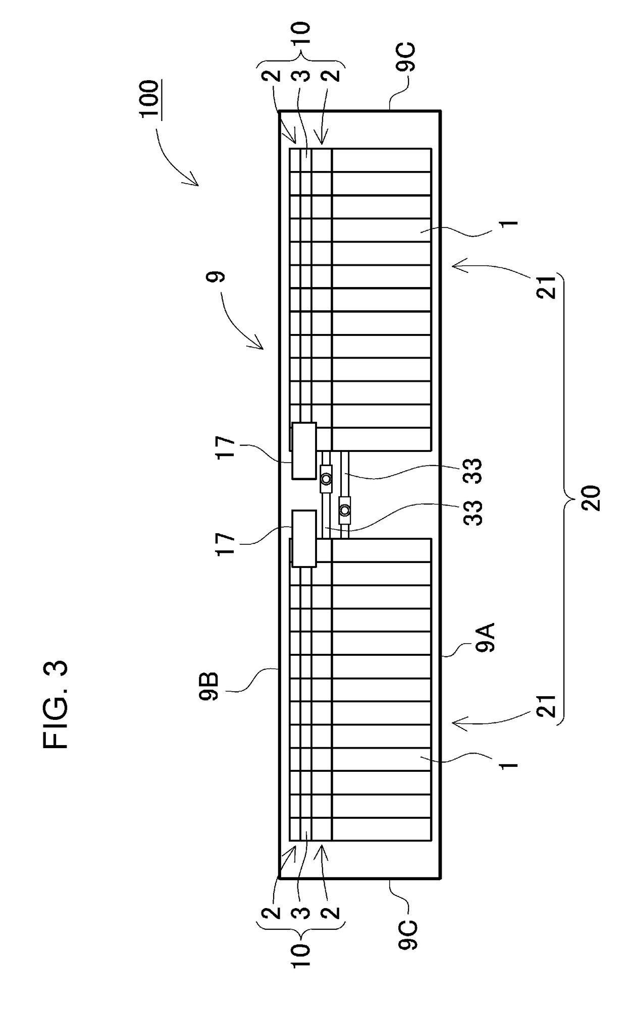
[0032]A battery system of FIGS. 1 to 3 is provided with: a plurality of battery units 2 which each have a plurality of battery cells; heat exchangers 3 which are disposed in a thermal-coupling state with this battery units 2, and are cooled by a coolant internally circulated coupled with cooling mechanism 35; and outer case 9 which houses these battery units 2 and heat exchanger 3.

(Battery Unit 2)

[0033]As shown in FIGS. 4 and 5, in battery unit 2, a pair of end plates 4 are disposed on both end faces of battery stacked body 7 where the plurality of battery cells 1 are stacked, and then the pair of end plates 4 are coupled by binding bars 5. Both ends of binding bar 5 are fixed at end plates 4, to fix stacked battery cells in a pressed state. Battery cell 1 of the figures is a rectangular parallelepiped battery (prismatic battery). In battery stacked body 7, battery cells 1 are stacked in the thickness direction with insulating separator 6 sandwiched between battery cells 1. Here, in...

embodiment 2

[0058]Further, as shown in FIGS. 9 to 11, in the battery system, battery unit 2 which is housed in outer case 9, can be disposed at a specific inclined posture. In battery system 200 shown in these figures, four pieces of battery blocks 10 are disposed in the same connecting state as above-mentioned battery system 100, but the inclined posture of each of battery blocks 10 is different from the above-mentioned embodiment. In battery system 200, each of battery blocks 10 is inclined in the right and left direction and in the front-back direction. Then, in each of battery blocks 10, three corners including the ends of the plus and minus output sides are elevated and away from base plate 9A of outer case 9.

[0059]In battery system 200 shown in FIGS. 9 to 12, the two pieces of battery units (B8, B7) disposed at the plus output side of series unit 20 are coupled, to constitute battery block 10. In the plan view (refer to FIG. 9), battery block 10 including battery units (B8, B7) is dispose...

embodiment 3

[0065]Further, the battery system can have a structure shown in FIGS. 14 to 16. In the battery system shown in the figures, the four pieces of the battery blocks which are housed in the outer case, has a different structure from the above-mentioned embodiments. As shown in FIG. 16, in battery block 10, two pieces of battery units 2 are arranged on the upper surface of heat exchanger 3. Then, heat exchanger 3 is disposed in the thermal-coupling state with the bottom surface 2A of battery units 2. Further, battery system 300 is provided with series unit 20 in which the eight pieces of battery units 2 are connected in series with the four battery blocks connected in series.

[0066]Further, series unit 20 is divided into a plurality of divided units 21 in which the plurality of battery units 2 are connected in series. Series unit 20 shown in the figures is divided into four pieces of divided units 21. One divided unit 21 has one battery block 10 which includes two pieces of battery units ...


PUM


Abstract

A battery system having: a series unit in which battery units are connected in series; heat exchangers thermally coupled with the battery units and internally circulating the coolant; and an outer case in which the series units and the heat exchangers are accommodated. The battery unit has battery cells stacked together, a plus output terminal and a minus output terminal at both ends thereof. The battery unit disposed at an end of the plus output terminal side of the series unit is disposed at an inclined posture where the end of the plus output terminal side is away from the base plate of the outer case. The battery unit disposed at an end of the minus output terminal side of the series unit, is disposed at an inclined posture where the end of the minus output terminal side is away from the base plate of the outer case.

Description

TECHNICAL FIELD[0001]The present invention relates to a battery system and an electric vehicle equipped with the battery system. A battery unit having a plurality of battery cells is housed in an outer case, and the battery system cools the battery unit by using a cooling mechanism.BACKGROUND ART[0002]The battery system of high power which is incorporated in a hybrid vehicle or an electric vehicle, has high current of charging and discharging. As such a battery system is used in many kinds of external conditions, a temperature of the battery cells constituting the battery unit may be increased. The temperature increase of the battery cell causes a life of the battery cell to be decreased. A battery system having a cooling mechanism for suppressing a temperature increase, has been developed. (refer to Patent Literature 1)[0003]The battery system described in Patent Literature 1, includes: a battery unit having a plurality of battery cells; an outer case housing the battery unit; and ...

Claims


Application Information

Patent Timeline
IPC IPC(8): H01M10/613H01M10/6568H01M10/625H01M10/6554H01M10/6552H01M2/10H01M2/34B60L11/18H01M50/209H01M50/24H01M50/249H01M50/51H01M50/583
CPCH01M10/613H01M10/6568H01M10/625H01M10/6554H01M10/6552H01M2/1077H01M2/34B60L11/187B60L11/1879H01M10/647H01M10/63Y02T10/70Y02E60/10H01M50/51H01M50/249H01M50/583H01M50/209H01M50/24B60L58/24B60L50/64
Inventor MOTOYOSHI, KENJINISHIKAWA, MASATO
Owner SANYO ELECTRIC CO LTD
Why Eureka
Try Eureka