
Method and apparatus for controlling access in next generation mobile communication system

a mobile communication system and access control technology, applied in electrical devices, connection management, security arrangements, etc., can solve problems such as data loss, transmission delay, data loss, etc., to improve voice over lte (volte) performance, enhance data, and extend coverage

Active Publication Date: 2019-02-07
SAMSUNG ELECTRONICS CO LTD
View PDF4 Cites 48 Cited by
  • Summary
  • Abstract
  • Description
  • Claims
  • Application Information

AI Technical Summary

Benefits of technology

The patent is about improving performance in wireless communication systems, specifically in LTE and the next generation mobile communication system. It discusses a method called packet delay tolerance, which adjusts discontinuous reception and repetitive retransmission to enhance speech and data transmission over LTE. By using this method, terminals can request longer periods of discontinuous reception and repetitive retransmission to improve delay tolerance and extend coverage. This can lead to better quality calls and faster data transfer. Overall, the patent provides a solution for improving the reliability and efficiency of wireless communication systems.

Problems solved by technology

In the next generation mobile communication system supporting a high data rate, if PDCP PDUs are lost or arrived late in a single connectivity environment, if PDCP PDUs are discarded at a transmitter because of the expiry of the PDCP expiry timer, or if one of two PDCP entities receives a PDCP PDU late in a dual connectivity environment, all the received data should be stored in a buffer until a reordering timer that is triggered at the receive PDCP layer expires, resulting in transmission delay.
If the memory or buffer capacity is not sufficient, data loss may occur.
If the data that has triggered the PDCP reordering timer arrives before the expiry of the timer or if the PDCP reordering timer expires, a large amount of data received while the timer is running may be delivered to the upper layer at one time and, thus, the upper layer is likely to fail to process all of the data, resulting in data loss.

Method used


Image

  • Method and apparatus for controlling access in next generation mobile communication system
  • Method and apparatus for controlling access in next generation mobile communication system
  • Method and apparatus for controlling access in next generation mobile communication system

Examples


embodiment 1

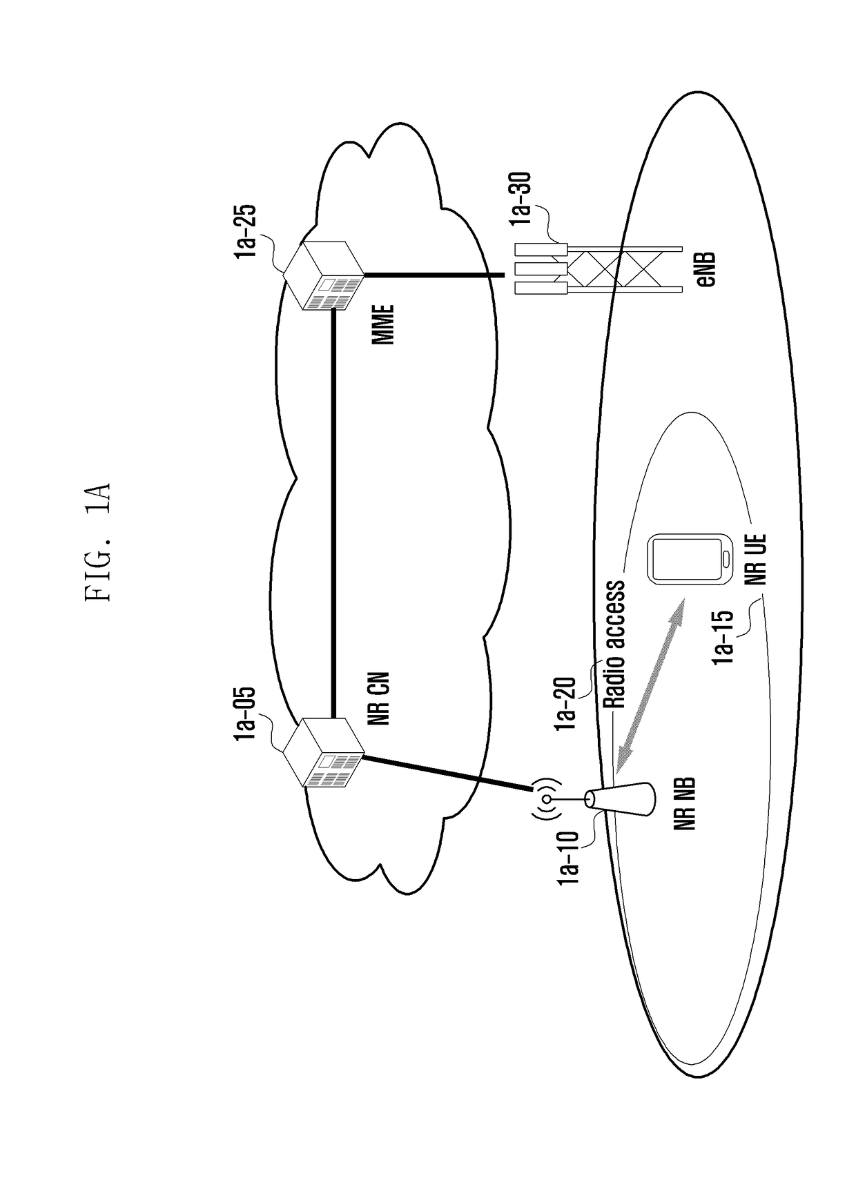
[0104]FIG. 1A is a diagram illustrating an architecture of a next generation mobile communication system according to an embodiment of disclosure.

[0105]Referring to FIG. 1A, a radio access network 1a-20 of the next generation mobile communication system includes a new radio Node B (NR NB) 1a-10 and a new radio core network (NR CN) 1a-05. A new radio user equipment (hereinafter, referred to as a new radio user equipment (NR UE) or simply UE) 1a-15 connects to an external network via the NR NB 1a-10 and the NR CN 1a-05.

[0106]In FIG. 1A, the NR NB 1a-10 corresponds to the evolved Node B (eNB) in the legacy LTE system. The NR UE 1a-15 connects to the NR NB, which may provide services superior to those of the legacy eNB. In the next generation mobile communication system where all user traffic is served through shared channels, there is a need of an entity for collecting UE-specific status information (such as buffer status, power headroom status, and channel status) and scheduling the U...

embodiment 1-1

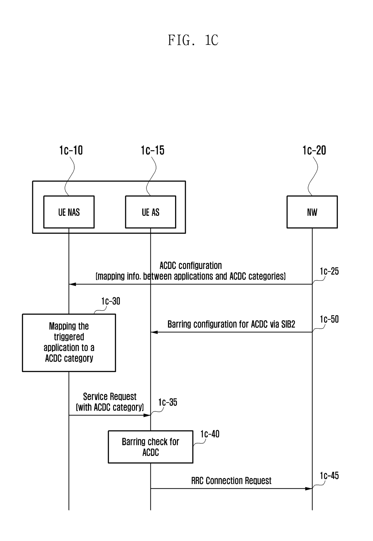
[0117]The disclosure proposes a method for mapping an access triggered by a UE NAS to a specific category. In the embodiment 1-1, the UE NAS maps an access to one category.

[0118]In embodiment 1-1, an access is mapped to at least one standardized access category. In addition, an access may not be mapped to any subcategory of the non-standardized access category provided by the network. In the disclosure, the categories provided by the network for use in mapping an access thereto are assigned at least one of predetermined priorities. The triggered access is mapped to a category with the highest priority among the categories to which the access can be mapped. In the disclosure, a category corresponding to “Emergency” belongs to a category set with the highest priority. A category corresponding to a “high priority access” may belong to the category set with the highest priority. The high priority access denotes a mobile communication operator-exclusive or public office-exclusive access,...

embodiment 1-2

[0137]In the embodiment 1-2, the UE NAS maps an access to a standardized access category and, additionally, a non-standardized access category to which the access can be mapped. In the disclosure, the service request that the UE NAS transmits to the UE AS includes the information indicating a standardized access category because the triggered access should be mapped to one standardized access category. At operation 1f-05, no access category list is provided by the UE AS. Accordingly, the operation of determining whether the access can be mapped to one of non-standardized access categories at operation 1f-25 is not performed based on the non-standardized access category included in the list. For example, the UE NAS determines whether there is a non-standardized access category based on only the information on non-standardized access categories supportable by the network that is provided through NAS signaling or application level signaling.

[0138]In embodiment 1-2, the UE NAS may send ...


PUM


Abstract

An apparatus and a method to apply 5G communication systems to IoT networks is provided. The apparatus includes technologies, such as a sensor network, machine type communication (MTC), and machine-to-machine (M2M) communication may be implemented by beamforming, multiple-input multiple-output (MIMO), and array antennas. Application of a cloud radio access network (RAN) as the above-described big data processing technology may also be considered to be as an example of convergence between the 5G technology and the IoT technology. The disclosure relates to a method and an apparatus for controlling network access in a next generation mobile communication system.

Description

CROSS-REFERENCE TO RELATED APPLICATION(S)[0001]This application is based on and claims priority under 35 U.S.C. § 119(a) of a Korean patent application numbers 10-2017-0098553, filed on Aug. 3, 2017, 10-2018-0001960, filed on Jan. 5, 2018, 10-2018-0003416, filed on Jan. 10, 2018, and 10-2018-0008417, filed on Jan. 23, 2018, in the Korean Intellectual Property Office, the disclosure of each of which is incorporated by reference herein in its entirety.BACKGROUND1. Field[0002]The disclosure relates to a method and an apparatus for controlling access in a next generation mobile communication system. More particularly, the disclosure relates to a receiver-triggered packet data convergence protocol (PDCP) status reporting-method in a next generation mobile communication system.2. Description of Related Art[0003]To meet the demand for wireless data traffic having increased since deployment of fourth generation (4G) communication systems, efforts have been made to develop an improved fifth ...

Claims


Application Information

Patent Timeline
Patent Type & Authority Applications(United States)
IPC IPC(8): H04W76/50H04W76/28H04W4/90H04W76/27H04W48/02H04W76/19
CPCH04W76/50H04W76/28H04W4/90H04W76/27H04W48/02H04W76/19H04W12/08
Inventor KIM, SANGBUMKIM, DONGGUNSAYENKO, ALEXANDERJANG, JAEHYUKJIN, SEUNGRIKIM, SOENGHUN
Owner SAMSUNG ELECTRONICS CO LTD
Learn More