

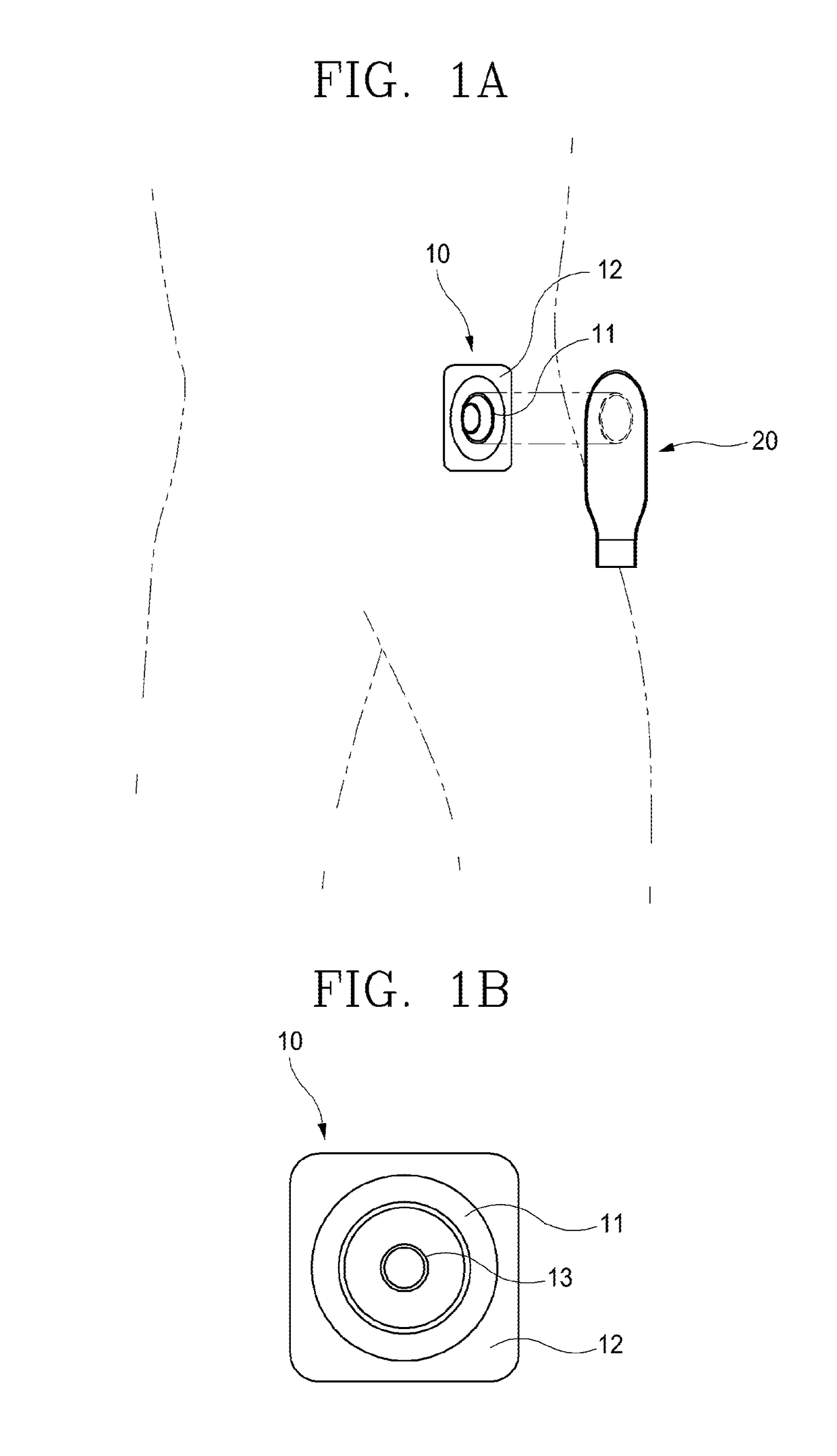
Device for cutting artificial anus protection plate
a technology for cutting devices and protection plates, applied in surgical instruments, medical science, surgery, etc., can solve the problems of increasing leakage, frequent replacement of artificial anus protection plates b>10/b> attached to the skin, and skin irritation, etc., to achieve convenient carrying and maintenance, convenient cutting, and easy attachment and removal
- Summary
- Abstract
- Description
- Claims
- Application Information
AI Technical Summary
Benefits of technology
Problems solved by technology
Method used
Image

Examples
third embodiment
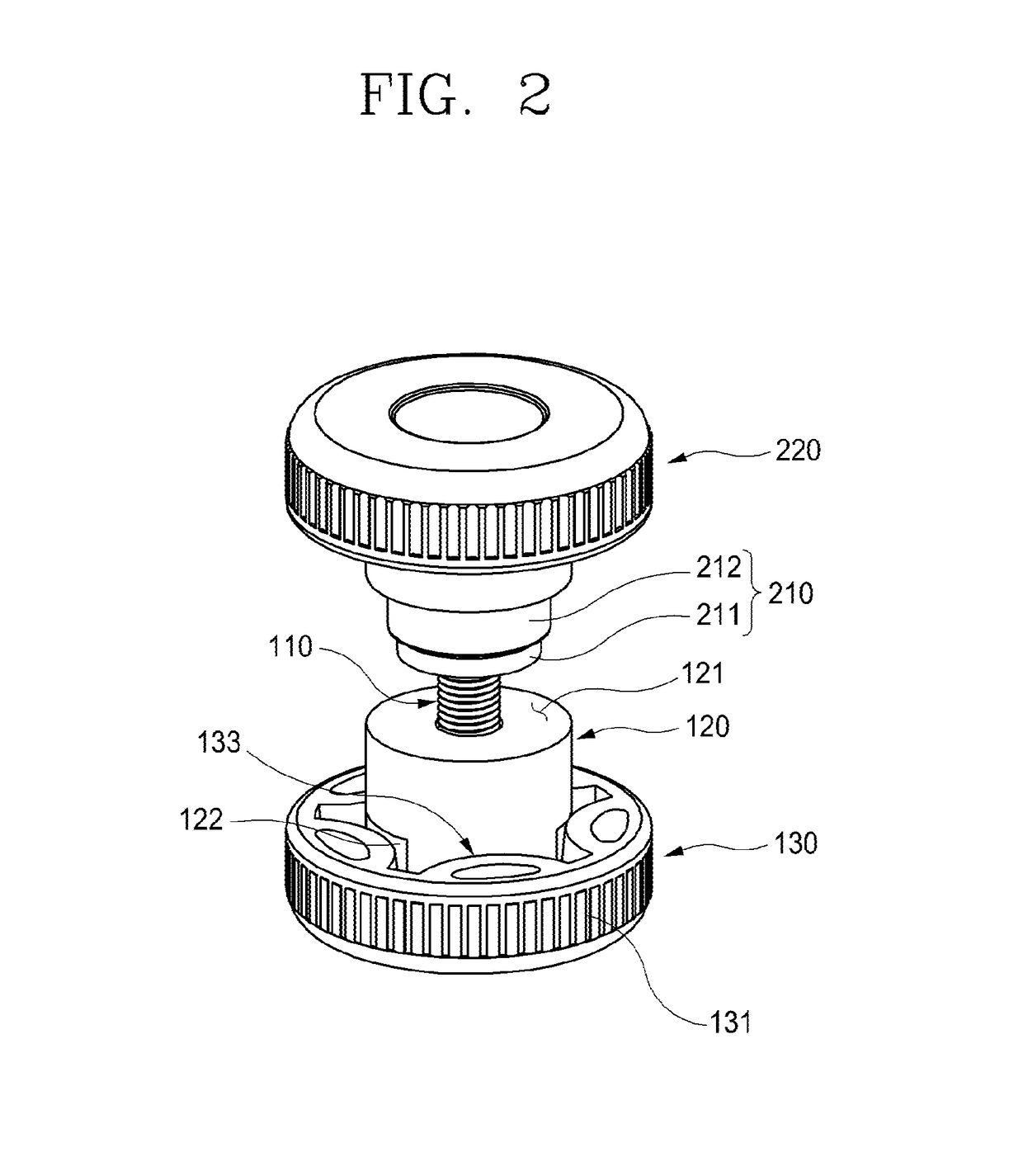
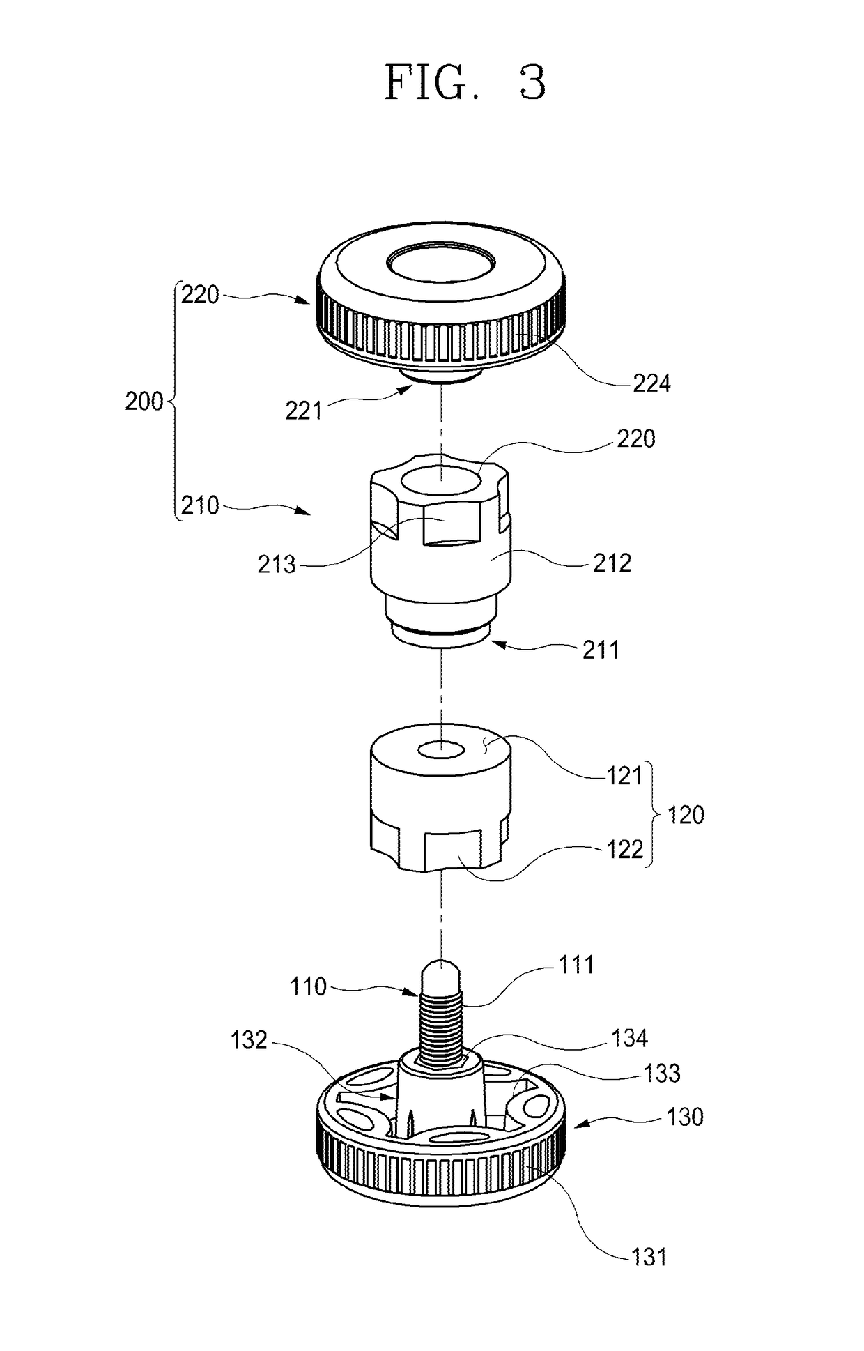
[0182]In a third embodiment, the cylinder part 610, as illustrated in FIGS. 14A and 14B, may be divided into an upper portion and a lower portion, the upper portion may be formed to have a relatively small outer diameter so as to be inserted into the pressing body part 620 to be described later, and the lower portion may be formed to have a larger diameter than the upper portion in order to be coupled to the pressing part 630 to be descried later.
[0183]Here, the outer diameter of the lower portion may have the same value as or a nearly approximate value to that of the pressing body part 620.
[0184]Meanwhile, the cylinder part 610 has a problem in that a portion of a finger is jammed in a boundary portion between the upper portion and the lower portion according to a vertical movement of the pressing body part 620, and to solve this problem, as illustrated in FIGS. 14A and 14B, a tapered section 613 in which the outer diameter thereof decreases toward the upper side thereof may be for...
second embodiment
[0185]In a second embodiment, the cylinder part 610, as illustrated in FIGS. 16A and 16B, may be divided into an upper portion and a lower portion, the upper portion may be formed to have a relatively small outer diameter so as to be inserted into the pressing body part 620 to be described later, and the lower portion may be formed to have a larger diameter than the upper portion to be coupled to the pressing part 630 to be descried later.
[0186]Here, the outer diameter of the lower portion may have the greater value than that of the pressing body part 620.
[0187]Meanwhile, the cylinder part 610 has a problem in that a portion of a finger is jammed in a boundary portion of the upper portion and the lower portion according to a vertical movement of the pressing body part 620, and to solve this problem, as illustrated in FIGS. 16A and 16B, a tapered section 613 in which the outer diameter thereof decreases toward the upper side thereof may be formed in the boundary portion between the u...
fourth embodiment
[0195]In a fourth embodiment, the pressing part 630, as illustrated in FIGS. 16A and 16B, may include a cylinder member 610 having a cylinder space section 638 is formed on an upper side thereof so that the outer peripheral surface of the cylinder part 610 is inserted and is vertically movable therein.
[0196]More specifically, the cylinder space section 638 is concavely formed in a cylindrical shape on an upper surface of the pressing part 630, and the second cylinder space S2 is formed such that the cylinder member 610 is inserted into the cylinder space section 638.
[0197]In addition, the cylinder member 610 receives a pressure moving downward due to an increase in the pressure in the second cylinder space S2 and an increase in volume according to the increase in the pressure, and the pressure is transferred to the cutting part 210 installed under the cylindrical member, so that the cutting part 210 cuts the artificial anus protection plate 10.
[0198]Meanwhile, on at least one among ...
PUM
 Abstract
Description
Claims
Application Information