Oven

a technology for ovens and ovens, applied in the field of ovens, can solve the problems of increased oven failure, consumer complaints, and difficult use of teflon at temperatures over 250° c., and achieve the effects of reducing the time required for oven cleaning, reducing the load of the oven, and reducing the time required for cleaning

Active Publication Date: 2019-02-14
SAMSUNG ELECTRONICS CO LTD
View PDF0 Cites 3 Cited by
  • Summary
  • Abstract
  • Description
  • Claims
  • Application Information

AI Technical Summary

Benefits of technology

[0019]The present disclosure is directed to providing an oven having a coating film having durability against repetitive heat load while having a liquid-repellent property capable of preventing contaminants such as oil or the like.
[0020]Further, the present disclosure is directed to providing a method for forming a coating film for an oven having durability against repetitive heat load while having a liquid-repellent property capable of preventing contaminants such as oil or the like.
[0021]Further, the present disclosure is directed to providing an oven capable of preventing contaminants from sticking to an inner wall of the oven by dropping oil droplets or water droplets having a small volume from the inner wall of the oven.

Problems solved by technology

However, it is necessary to perform the Pyro cleaning one to three times a year though it depends on a use situation and a contamination state.
In this case, a failure of the oven is increased, which resulted in consumer complaints.
However, since Teflon is weak in the high temperature and generates harmful gas at the high temperature, it is difficult to use Teflon at temperatures over 250° C., such as the inner wall of the oven.
Even if a material having another liquid-repellent component is used, the liquid repellency is lost when exposed to a temperature environment of 420° C., such as the Pyro cleaning, and an effect of preventing contamination cannot be expected.
Therefore, conventionally, when a coating film having the liquid repellency is applied to the inner wall of the oven, a Pyro cleaning function was not provided.
However, conventionally, it has not been known how to form the coating film having the liquid repellency on the inner wall of the oven so that the cracks do not occur in the repetition of the heat load.
Further, a method of forming the coating film having the above-described characteristics on the inner wall of the oven has not been specifically known.
In particular, it is difficult to form the coating film having a large film thickness to ensure durability against the heat load.
That is, a small spotty contaminant could remain even though the inner wall of the oven has the coating film.
Patent Document 2 does not disclose removing the oil droplets or water droplets of the small volume continuously adhered even when the coating film is provided.
If the contaminants are denatured by the heat applied repeatedly during the cooking process and turned black, the contaminants become noticeable.
Therefore, there is also a demand for a method that makes it difficult for the small oil stain to stick to the coating film or to easily clean the small oil stain.
In addition, the coating film may have a surface property in which a water contact angle is 100° or more in order to make it difficult for the contaminants by oil or moisture generated from the food to be cooked to stick to the cooking chamber inner wall.
The droplets adhering to the cooking chamber inner wall may be deteriorated by repeated heating.
Even if the contaminants adhere to the coating film for some reason, the contaminants can be dropped by heat.
Further, the contaminant collecting portion may be formed on a window of the door for inserting or removing the food to be cooked in the cooking chamber.
According to an oven of the present disclosure, since a coating film having a thickness of 0.2 μm or more and 3 μm or less is formed on a cooking chamber inner wall, it may be difficult for contaminants caused by oil or the like to be adhered to the cooking chamber inner wall due to a liquid repellency of the coating film.
More particularly, conventionally, it has been thought that if temperatures of a cooking chamber and the cooking chamber inner wall are not maintained at a very high temperature of 420° C. as in a Pyro cleaning, the adhered contaminants derived from oil or the like cannot be dropped.

Method used


Image

  • Oven
  • Oven
  • Oven

Examples


first embodiment

[0165]An oven 100 according to the present disclosure will be described with reference to a respective drawing.

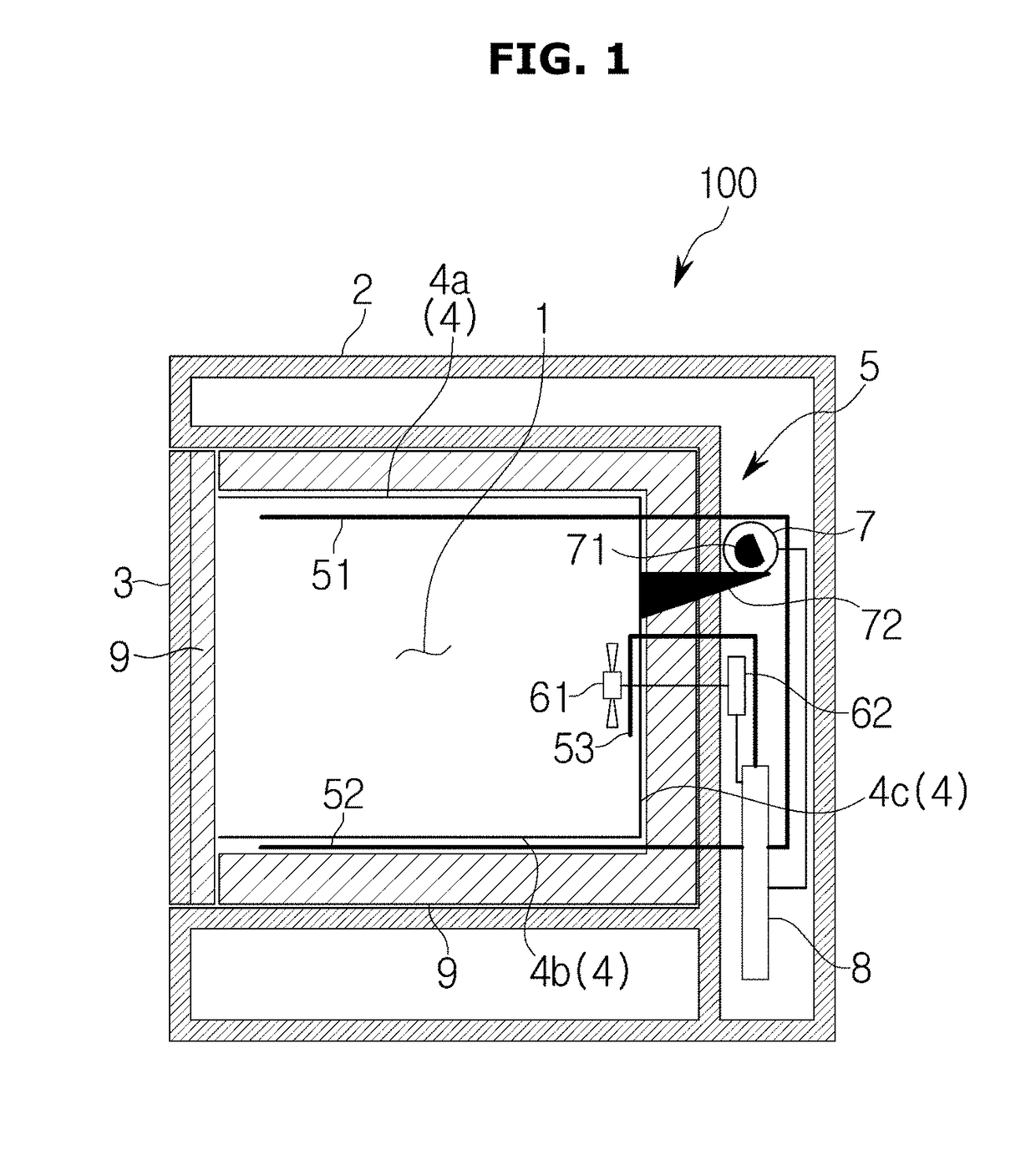
[0166]As shown in FIG. 1, the oven 100 may be configured such that a food to be cooked is received in a cooking chamber 1, and the food to be cooked is heated by a heater 5. Particularly, the oven 100 may include a main body 2 forming an appearance. The main body 2 may have a substantially rectangular parallelepiped shape with its front surface opened. Further, the oven 100 may further include the cooking chamber 1 provided inside the main body 2. The cooking chamber 1 may have a substantially rectangular parallelepiped shape with its front surface opened. The cooking chamber 1 may be defined by a cooking chamber inner wall 4. The cooking chamber inner wall 4 may include an upper face 4a, a lower face 4b, a right face, a left face, and a rear face 4c. Further, the oven 100 may further include a door 3 rotatably installed at the main body 2 to open or close the cooking chamb...

second embodiment

[0225]As described above, in the oven 100 of the second embodiment, the droplets including the small water droplets or the oil droplets can be separated from the cooking chamber inner wall 4 and be dropped by slightly vibrating the cooking chamber inner wall 4 in the vertical direction by the vibrator 7 after the temperature inside the cooking chamber 1 is maintained at 60° C. or higher by the heater 5 in the cleaning mode.

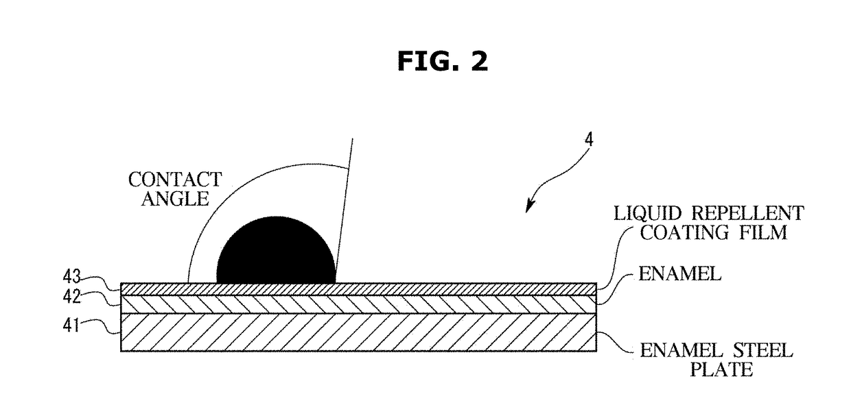
[0226]The droplets having a large droplet diameter may be dropped by their own weight due to the liquid repellency of the coating film 43, and the small droplets adhered to the coating film 43 having the liquid repellency may be moved and dropped by an action of the heater 5 and the vibrator 7.

[0227]Therefore, the water droplets or the oil droplets remaining on the cooking chamber inner wall 4 can be substantially removed. As a result, the small oil droplets, which are continuously adhered to the cooking chamber inner wall 4 and deteriorated by the heat during coo...

third embodiment

[0231]Next, the oven 100 will be described with reference to the drawings.

[0232]As shown in FIG. 12, the oven 100 of the third embodiment is different from the oven 100 of the first embodiment and the second embodiment in that the vibrator 7 is not provided. In addition, the oven 100 of the third embodiment is different from the oven 100 of the first embodiment and the second embodiment in a configuration of the control board 8 related to the cleaning mode.

[0233]More particularly, in the cleaning mode for dropping the contaminant adhering to the cooking chamber inner wall 4, the control board 8 (the controller) may drive the heater 5 so that the temperature of the cooking chamber inner wall 4 is maintained at 350° C. or higher and 400° C. or lower for a predetermined holding time or longer while simultaneously driving the fan 61. That is, this embodiment differs from the conventional Pyro cleaning in that the fan 61 is driven when the inside of the cooking chamber 1 and the cooking...


PUM

PropertyMeasurementUnit
surface energyaaaaaaaaaa
distanceaaaaaaaaaa

Abstract

Provided is an oven having an improved structure for keeping a cooking chamber clean. The oven includes a main body, a cooking chamber provided inside the main body, a main heater disposed inside the cooking chamber, a fan disposed inside the cooking chamber to circulate air heated by the main heater, a coating film formed on at least a part of a cooking chamber inner wall and having a liquid repellency, and a contaminant collecting portion having a liquid repellency smaller than that of the coating film and provided on the cooking chamber inner wall with which air circulated by the fan collides.

Description

CROSS-REFERENCE TO RELATED APPLICATIONS AND CLAIM OF PRIORITY[0001]This application is a 371 National Stage of International Application No. PCT / KR2017 / 001500 filed Feb. 10, 2017, which claims priority to Japanese Patent Application No. 2016-024939 filed Feb. 12, 2016, Japanese Patent Application No. 2016-027667 filed Feb. 17, 2016, Japanese Patent Application No. 2016-027669 filed Feb. 17, 2016, Japanese Patent Application No. 2016-091953 filed Apr. 28, 2016, and Japanese Patent Application No. 2017-010770 tiled Jan. 24, 2017, the disclosures of which are herein incorporated by reference in their entirety.BACKGROUND1. Field[0002]The present disclosure relates to an oven, more particularly, to an oven having an improved structure for keeping a cooking chamber clean.2. Description of Related Art[0003]In the conventional electric oven, when a surface of an inner wall of the oven is contaminated by oil or the like discharged from a food to be cooked, a user has cleaned the oven on his / ...

Claims


Application Information

Patent Timeline
Patent Type & Authority Applications(United States)
IPC IPC(8): F24C15/00C09D1/00C09D5/16F24C14/00
CPCF24C15/005C09D1/00C09D5/16F24C14/00
Inventor IWAMOTO, KIYOSHIURAI, YASUSHIHAYASHI, SHIGEKISATO, SEIJIDOI, TOSHIHIROTAKENOSHITA, KAZUTOSHIKIDA, YURIKA
Owner SAMSUNG ELECTRONICS CO LTD
Why Eureka
Try Eureka