Light source device and electronic apparatus
- Summary
- Abstract
- Description
- Claims
- Application Information
AI Technical Summary
Benefits of technology
Problems solved by technology
Method used
Image
Examples
modification example 1
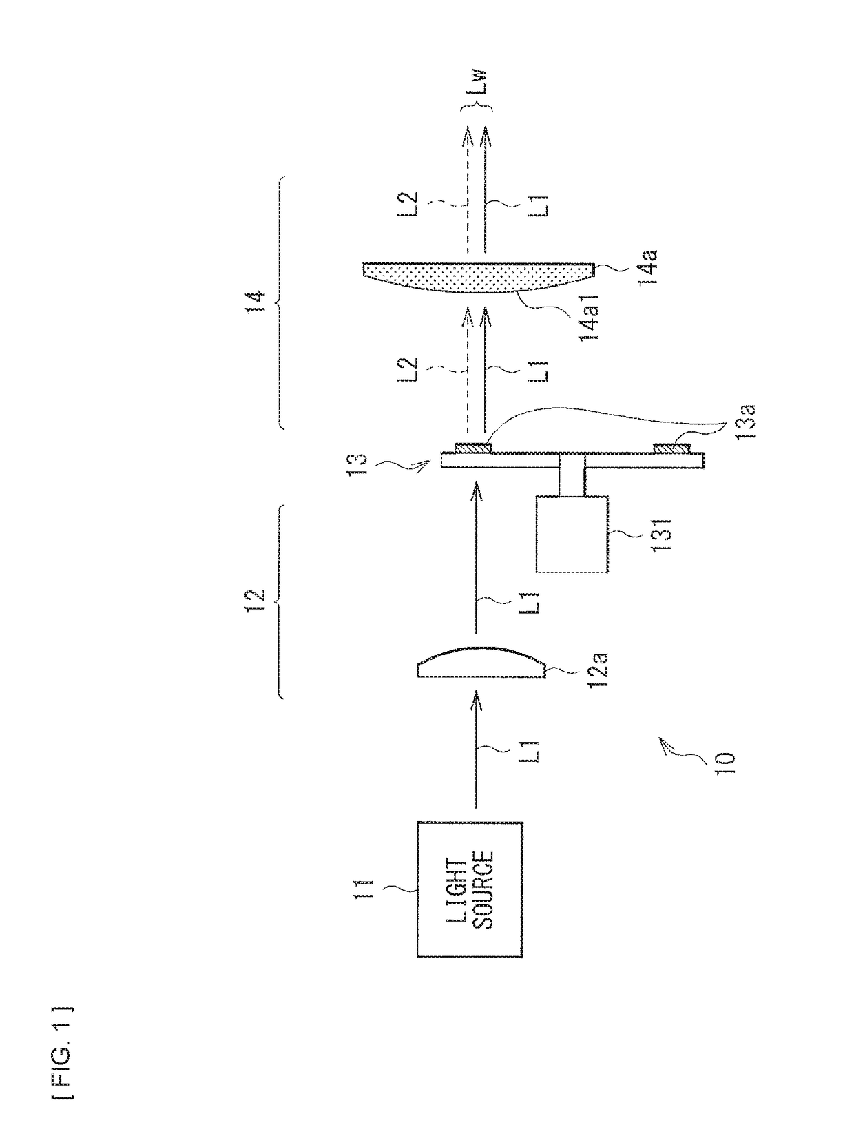
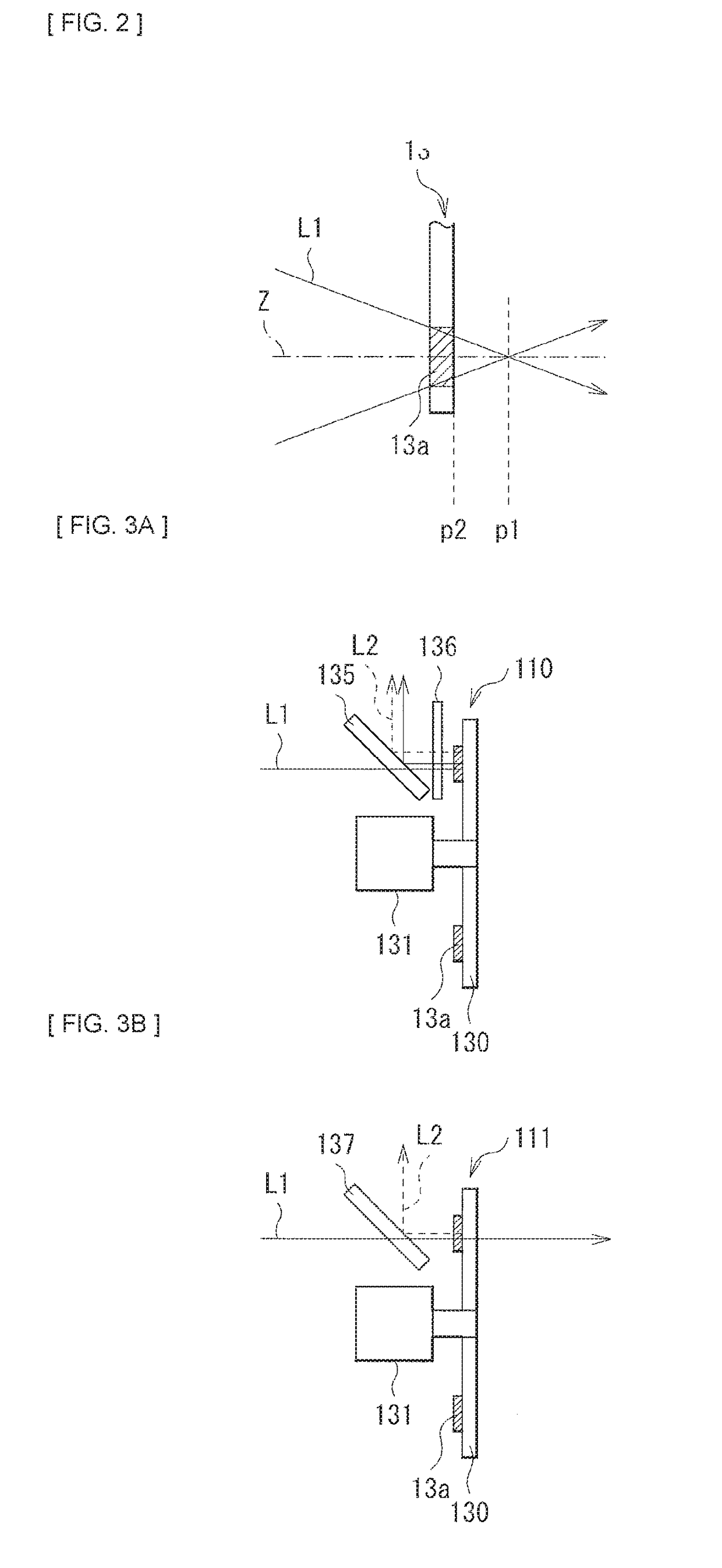
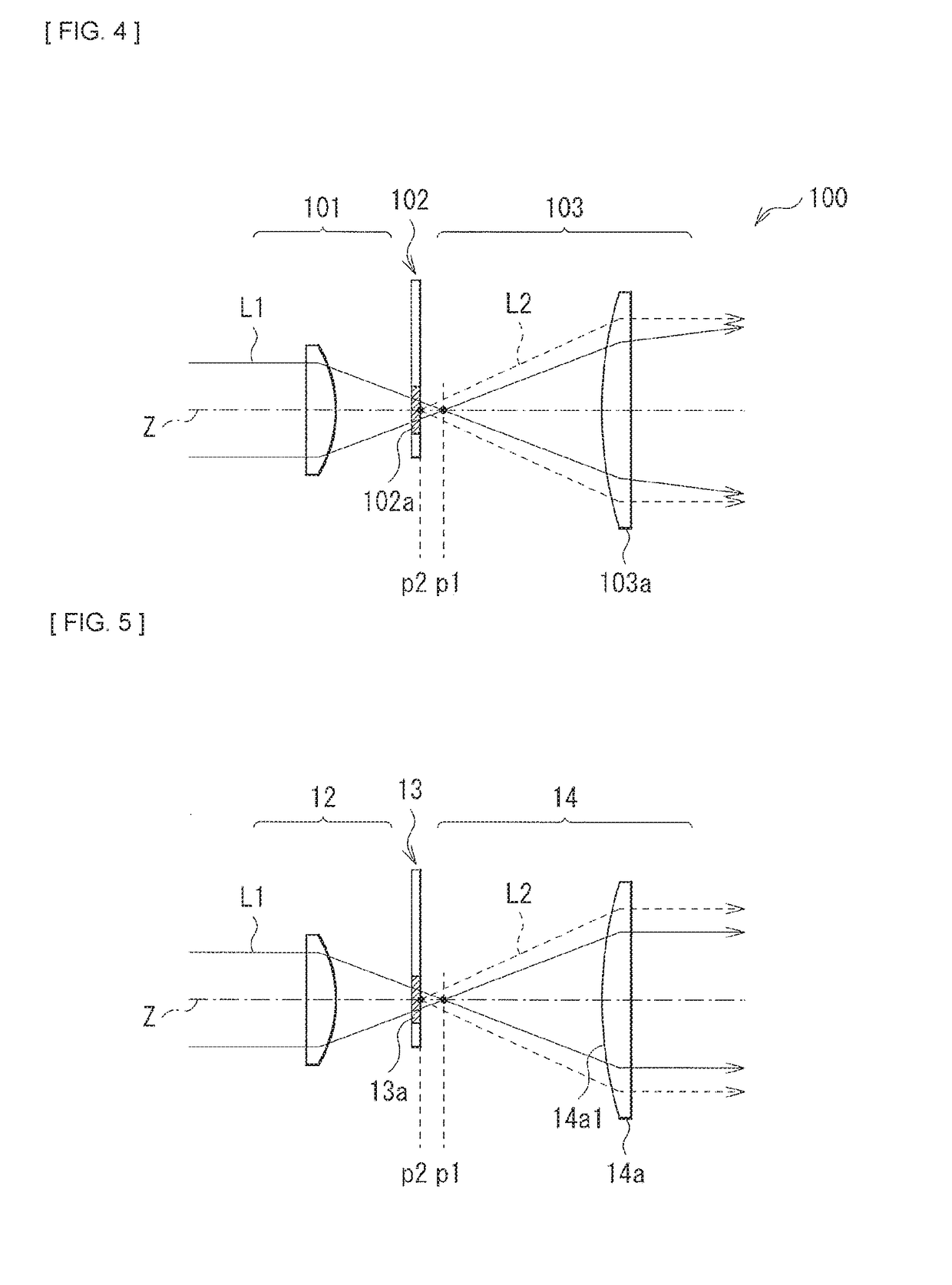
[0067]FIG. 6 illustrates a configuration of a main part of a light source device according to modification example 1. In this light source device, as with the foregoing first embodiment, the condensing optical system 12, the wavelength conversion element 13, and the collimating optical system 14 are disposed on the optical axis Z in order from side of the light source 11 (unillustrated in FIG. 6). Furthermore, this light source device outputs, for example, the white light Lw as illumination light by color mixture of color light (light L1) emitted from the light source 11 and fluorescence (light L2) in the wavelength conversion element 13. In the condensing optical system 12, a focal position of the light L1 is set to the position P1 shifted from the position P2 on the wavelength conversion element 13. The collimating optical system 14 includes an optical member that concentrates light on a different position for each wavelength.
[0068]However, in this modification example, a lens tha...
modification example 2
[0071]FIG. 8 illustrates a configuration of a main part of a light source device according to modification example 2. In this light source device, as with the foregoing first embodiment, the condensing optical system 12, the wavelength conversion element 13, and the collimating optical system 14 are disposed on the optical axis Z in order from the side of the light source 11 (unillustrated in FIG. 8). Furthermore, this light source device outputs, for example, the white light Lw as illumination light by color mixture of the color light (light L1) emitted from the light source 11 and the fluorescence (light L2) in the wavelength conversion element 13. In the condensing optical system 12, a focal position of the light L1 is set to the position P1 shifted from the position P2 on the wavelength conversion element 13. The collimating optical system 14 includes an optical member that concentrates light on a different position for each wavelength.
[0072]However, in this modification example...
second embodiment
[Configuration]
[0075]FIG. 10 illustrates a configuration of a light source device (a light source device 10A) according to a second embodiment of the disclosure. In this light source device 10A, as with the foregoing first embodiment, the condensing optical system 12, a wavelength conversion element 15, and the collimating optical system 14 are disposed in order from side of the light source 11. Furthermore, the light source device 10A outputs, for example, the white light Lw as illumination light by color mixture of the color light (light L1) emitted from the light source 11 and the fluorescence (light L2) in the wavelength conversion element 15. Moreover, also in the present embodiment, a focal position of the light L1 set by the condensing optical system 12 is set to a position shifted from a position on the wavelength conversion element 15 (as with the case with the condensing optical system 12 and the wavelength conversion element 13 illustrated in FIG. 2).
[0076]As with the wav...
PUM
 Abstract
Description
Claims
Application Information
 - R&D Engineer
- R&D Manager
- IP Professional
- Industry Leading Data Capabilities
- Powerful AI technology
- Patent DNA Extraction
Browse by: Latest US Patents, China's latest patents, Technical Efficacy Thesaurus, Application Domain, Technology Topic, Popular Technical Reports.
© 2024 PatSnap. All rights reserved.Legal|Privacy policy|Modern Slavery Act Transparency Statement|Sitemap|About US| Contact US: help@patsnap.com


