
Grounding Switch for Use in Metal-Clad Switchgear

a metal-clad switch and grounding switch technology, applied in the field of electric switches, can solve the problems of large energy consumption of the system, inability and large space requirements, and achieve the effect of severely burning or killing the electrician conducting maintenance or repair, and not having a way of grounding switches to meet the requirement of all live parts or buses being insulated without adding additional compartments

Active Publication Date: 2019-02-14
BENSON SETH
View PDF0 Cites 2 Cited by
  • Summary
  • Abstract
  • Description
  • Claims
  • Application Information

AI Technical Summary

Benefits of technology

The present invention is a metal-clad ground switch that can be installed in electrical power systems to protect electricians on the site. It is a modification to a typical grounding switch that automatically opens the insulation system in case of maintenance operation to allow the live parts to be grounded. This invention can replace the Ground and Test Device that requires removal of a circuit breaker and insertion of the Ground and Test Device, as it is insulated and in the switchgear during normal or emergency operation-only maintenance mode.

Problems solved by technology

Unfortunately, present grounding switches do not have a way of meeting the ANSI / IEEE metal clad requirement of all live parts or bus being insulated without adding additional compartments, space requirements, and significant cost.
If something goes wrong during the connection or thereafter, the energy of the system is known to be so great that it would severely burn or kill the electrician conducting maintenance or repair.

Method used


Image

  • Grounding Switch for Use in Metal-Clad Switchgear
  • Grounding Switch for Use in Metal-Clad Switchgear
  • Grounding Switch for Use in Metal-Clad Switchgear

Examples


first embodiment

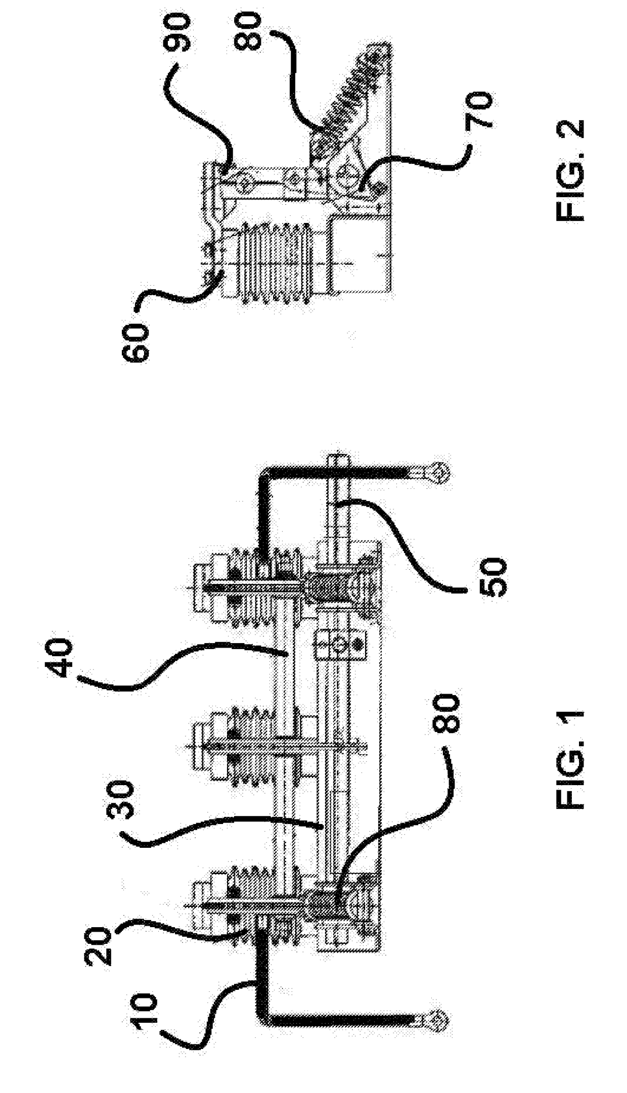
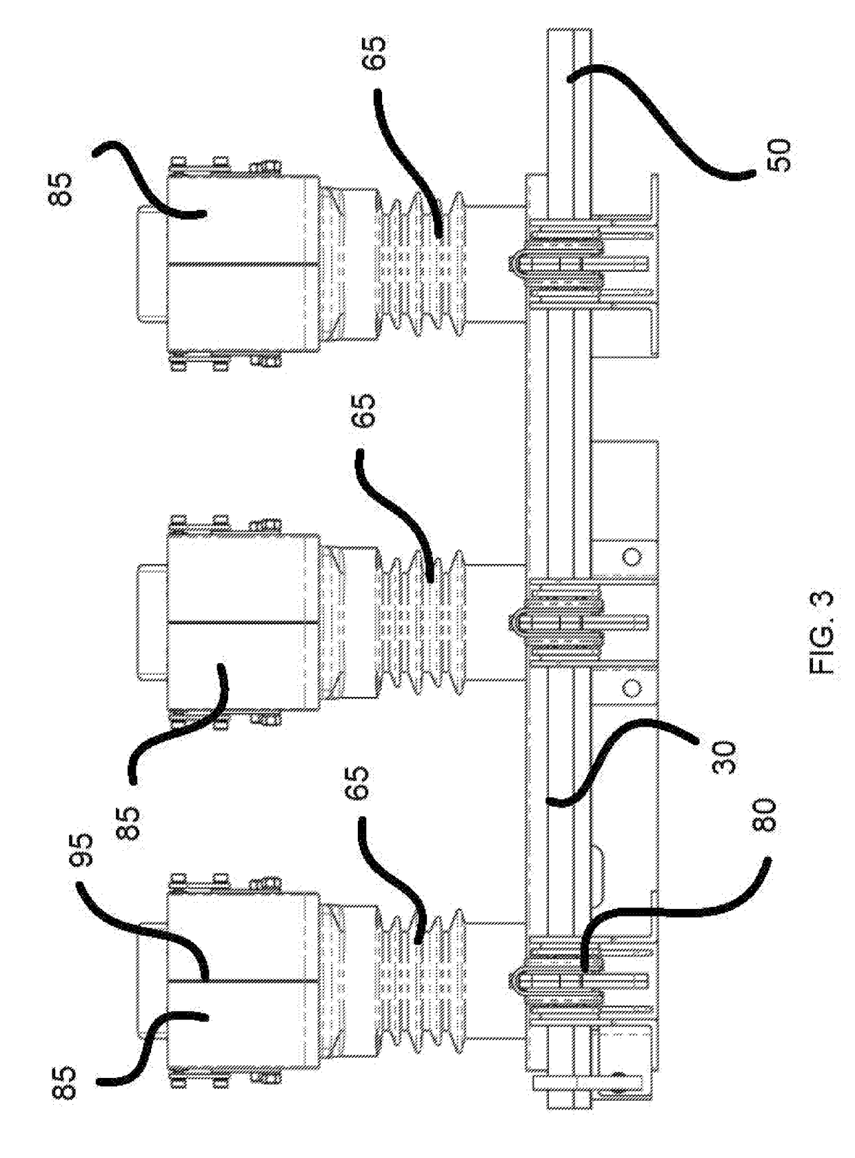
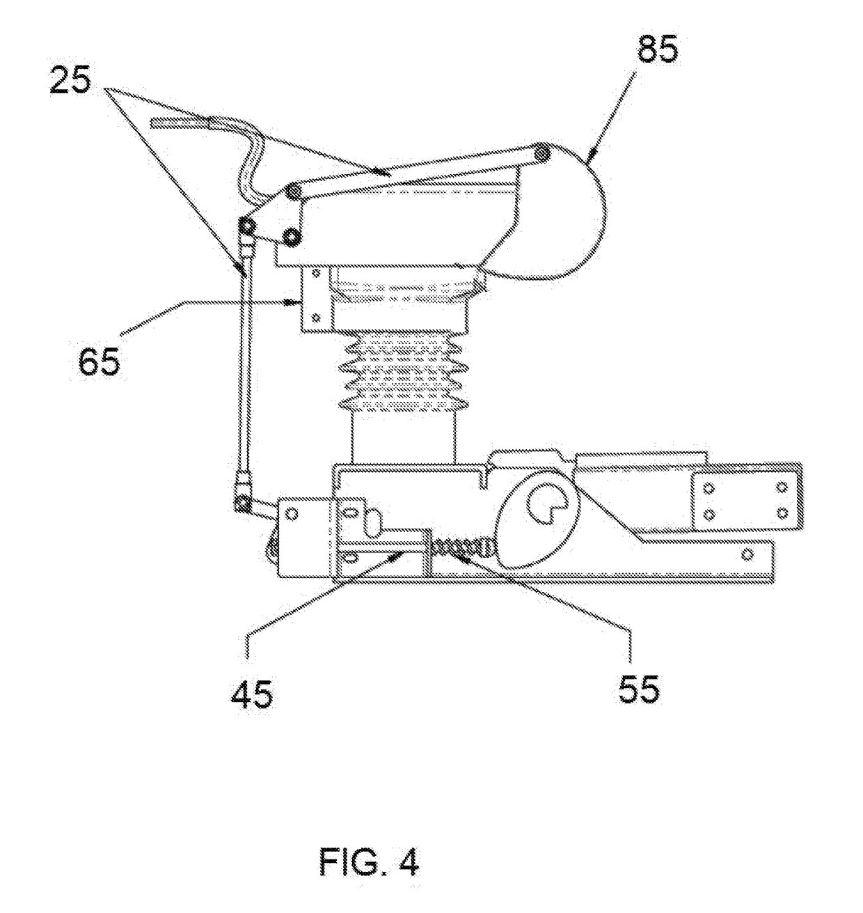
[0028]Differences between the alternate preferred embodiment disclosed in FIGS. 3-5 and the first embodiment disclosed in FIGS. 1-2 include a larger overall height of the standoff in order to accommodate a higher BIL rating to facilitate operation of an internal voltage sensor, and also to potentially provide for operation with higher voltage levels in general. Additionally, the insulated clam shell (85) is preferably of a break-away construction as a fail-safe mechanism.

[0029]Another difference between the two embodiments is that a steel cable is employed to manipulate the insulated clam shell (85) in the first embodiment, whereas the alternate preferred embodiment employs the spring (55) and aluminum rod (45) to manipulate the insulated clam shell (85). When the insulated clam shell (85) of the present invention closes (as the main switch blades of the switch gear open), the aluminum rod (45) drives the insulated clam shell (85) closed, compressing the spring. To reverse, the spri...

third embodiment

[0033]Alternate embodiments of the present invention may be designed to be smaller than those disclosed in the figures. The smaller, more compact version of the device of the present preferably employs linear motion instead of rotational motion of the main contacts to close. Additionally, other embodiments may alter the means by which the insulation opens in order to allow a contact to penetrate the insulation system. A third embodiment exhibits a switch design equipped with an insulation system that is pushed open / out of the way by the contacts, instead of opening via linkages.


PUM


Abstract

A metal-clad compliant grounding / earthing switch device configured for use within conventional switchgear is described. The device is equipped with adequate and compliant insulation of all bus connections, and is configured to close during maintenance outages grounding the live parts of the circuit feed by a particular breaker. The device enables electricians to perform maintenance and repairs in the event of an outage safely, and without the need to manually install a temporary Ground-and-Test Device. An insulated clam shell is present to limit fault propagation from live components until components are confirmed as grounded prior to maintenance of the switchgear.

Description

CONTINUITY[0001]This application is a non-provisional patent application of provisional patent application number 62 / 543,197, filed on Aug. 9, 2017, and priority is claimed thereto.FIELD OF THE PRESENT INVENTION[0002]The present invention relates in general to electrical switches, and more specifically relates to a new form of grounding / earthing switch configured for use in ANSI metal-clad switchgear such that the metal-clad requirement for insulated bus and associated connections is maintained.BACKGROUND OF THE PRESENT INVENTION[0003]It is known that, in a conventional electric power system, switchgear is disposed in communication with the system. Switchgear conventionally contains an assortment of disconnect switches, circuit breakers, insulators, and fuses, configured to facilitate repairs of the electric power system. Conventionally, switchgear is employed to de-energize portions of the system such that repairs / maintenance may be performed and faults may be cleared, ensuring ele...

Claims


Application Information

Patent Timeline
IPC IPC(8): H02B11/133H02B13/02H02B11/18H02B11/24H02B11/28
CPCH02B11/133H02B13/02H02B11/18H02B11/24H02B11/28H01H31/003H01H31/16H02B1/16H02B1/14
Inventor BENSON, SETH
Owner BENSON SETH
Learn More