Ultrasound transducer holder

a transducer and ultrasonic technology, applied in ultrasonic/sonic/infrasonic image/data processing, ultrasonic/sonic image/data processing, applications, etc., can solve the problems of musculoskeletal disorders, manual process can be tiring for the technician, and the ultrasonic procedure is not always reproducible between different technicians or scans, etc., to achieve a higher elastic modulus

Active Publication Date: 2019-02-21
BERI SERENA
View PDF0 Cites 5 Cited by
  • Summary
  • Abstract
  • Description
  • Claims
  • Application Information

AI Technical Summary

Problems solved by technology

The results from an ultrasound procedure are not always reproducible between different technicians or scans.
Furthermore, the manual process can be tiring for the technician and can cause musculoskeletal disorders due to sustained forces applied in unnatural positions.

Method used


Image

  • Ultrasound transducer holder
  • Ultrasound transducer holder
  • Ultrasound transducer holder

Examples


example 1

of a Soft Robotic Ultrasound Transducer Holder

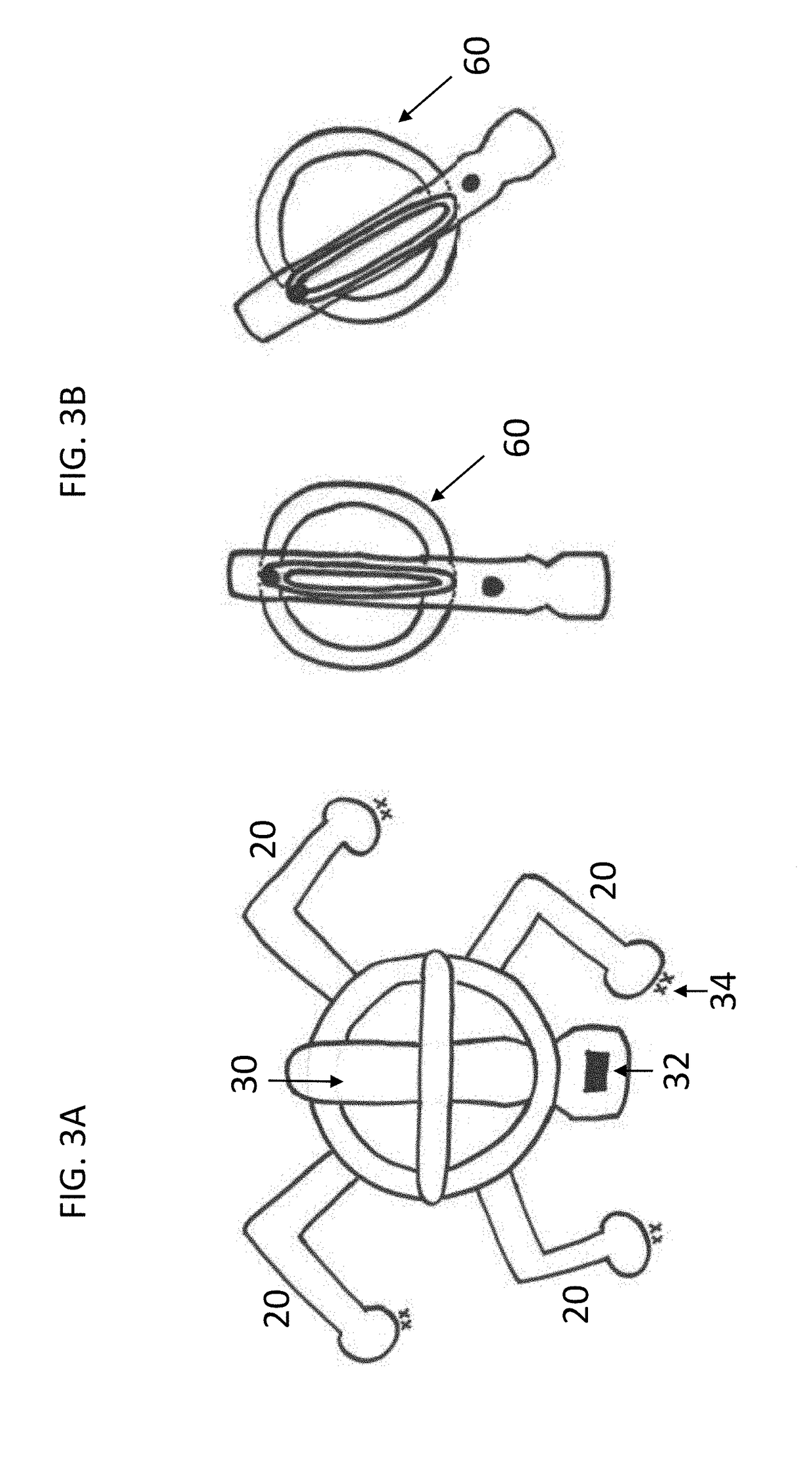
[0072]The soft robotic actuator (20, 22) has an air inlet (36) and two semicircular air channels (38) and can move in different directions based on air flow. If one chamber (38) is pressurized, then the soft actuator (20, 22) bends. If both air chambers (38) are pressurized, then the soft actuator (20, 22) elongates and gives linear actuation. If various actuators are controlled with an on / off pulse, the actuators can walk.

[0073]Linear actuators (22) are placed in the holder base horizontally. The holder has a center recess of 50.8 mm on the octagon and the probe has a diameter of 25.4 mm, so there is a clearance gap of 25.4 mm to which probe (30) can be tilted. The angle relationship is given in Tables 2 and 3.

TABLE 2Tilt angle with linear actuator movementActuator Movement (mm)6.3512.7019.0525.4Tilt Angle, degrees4°8°12°16°

TABLE 3Vertical height adjustment with tilt angleTilt Angle, degrees4°8°12°16°Height change (mm)0.341.363.055.41

[0...

example 2

g an Echocardiogram

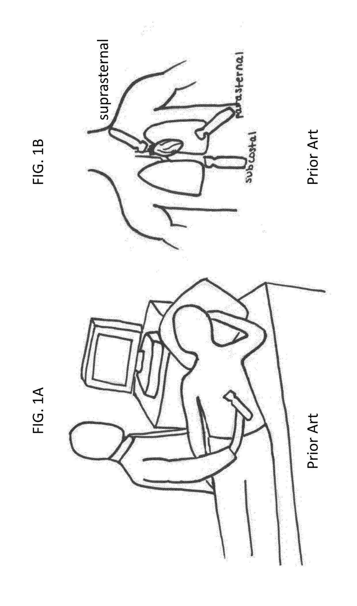
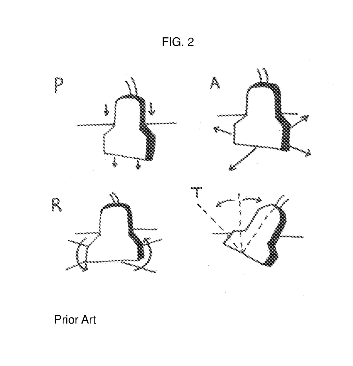
[0075]The devices described herein may be used to perform an echocardiogram to obtain different ultrasound image views of the heart. A technician or operator will mount ultrasound transducer (30) in base (10) and / or top frame (16). Ring (18) in the center of top frame (16) will snap around probe (30) to keep it in place. Top frame (16) is adjustable in height so probe (30) can be adjusted up or down in the assembly during mounting. Once transducer probe (30) is mounted in assembly (70), the assembly can be placed on the chest of a subject above the heart. A strap or belt can be used if needed to hold maintain general position. The air source is then turned on and probe (30) can be directed to move to a specific location by interacting with the microprocessor. The assembly can be manipulated to tilt transducer (30) to obtain ultrasound images of the heart at different angles. Three views of the heart that can be imaged include the parasternal long axis view, which ...

example 3

g Musculoskeletal Conditions in Motion

[0076]An ultrasound technician attaches the transducer holder to a patient with musculoskeletal pain. The patient reports significant pain and spasms in his shoulder when raising his arm. The straps on the transducer holder keep the transducer probe in close contact with the patient's shoulder, such as when the patient raises their arm. The transducer holder positions the ultrasound transducer in close proximity to a joint, ligaments, muscles, and / or nerves of the shoulder of the patient, e.g., while the patient is in motion, thereby assisting the technician in analyzing the patient's condition while freeing the hands of the technician to perform other tasks during the procedure. A series of imaging tests can be performed that assist the technician with diagnosing the patient's condition. The results of the imaging tests can be used, e.g., in combination with artificial intelligence and data mining from the captured images, to predict positions ...


PUM


Abstract

Described herein are devices and methods useful in automating ultrasound imaging. The device include a base coupled with soft robotics, which may be attached to an ultrasound transducer probe in order to robotically manipulate the probe to perform an ultrasound scan. The device has an adjustable structure configured to hold the probe on a walking soft robot. The device can be configured to be attached to, or worn by, the patient. With soft robotic actuation and locomotion, the holder can move and position the probe during a real time ultrasound scanning procedure. Furthermore, the holder may be equipped with sensors to sense and map pressure and location. The position of the holder can be robotically monitored and controlled so as to achieve consistency and reproducibility between ultrasound scans. Due to the wearable nature of the holder, the scans may be conducted while the patient is in motion, thereby providing a portable solution for ultrasonic imaging. The holder is cost effective and may be used in conjunction with various ultrasound probes.

Description

BACKGROUND OF THE INVENTION[0001]Ultrasound imaging is a routine method for probing the human body and for use in various diagnostic tests. Generally, an ultrasound transducer is manually placed onto the body by a technician (a sonographer) and an image is viewed in real time on a monitor (FIGS. 1A-1B). After viewing the image, the technician then moves the probe to obtain a desired image scan. Due to its manual nature, the output of an ultrasound procedure is highly dependent on the experience and capability of the technician performing the procedure. The results from an ultrasound procedure are not always reproducible between different technicians or scans. Furthermore, the manual process can be tiring for the technician and can cause musculoskeletal disorders due to sustained forces applied in unnatural positions. Thus, a need exists for an ultrasound device that can automate the process of performing ultrasound imaging in order to achieve uniform, consistent, and reproducible ul...

Claims


Application Information

Patent Timeline
Patent Type & Authority Applications(United States)
IPC IPC(8): A61B8/00A61B8/08A61B8/14
CPCA61B8/4218A61B8/4427A61B8/4227A61B8/5207A61B8/14A61B8/4254A61B8/0883B25J9/142B25J18/06
Inventor BERI, SERENA
Owner BERI SERENA
Why Eureka
Try Eureka