Calibration method for compensating home position of three-dimensional printer

a three-dimensional printer and home position technology, applied in the direction of dynamo-electric converter control, process and machine control, instruments, etc., can solve the problems of consuming time and labor, affecting the fineness of printed products, and the home position of three-dimensional printers cannot be accurately determined, so as to achieve the effect of increasing circuit costs

Inactive Publication Date: 2019-02-28
XYZPRINTING +1
View PDF0 Cites 9 Cited by
  • Summary
  • Abstract
  • Description
  • Claims
  • Application Information

AI Technical Summary

Benefits of technology

[0005]The present disclosure is directed to a calibration method for compensating a home position of a three-dimensional printer so as to solve problems of increasing circuit costs, complicating designs of control circuits, and occupying larger space for installation.

Problems solved by technology

Since the 3D printer may be easily affected by unpredictable vibration, oscillation, or interference of external force or mechanical structure itself, the three-axis home positions cannot be accurately determined.
For example, the Z-axis fails to arrive its actual home position due to vibration, oscillation, or interference of external force or mechanical structure itself after the home-position operation, and therefore to affect the fineness of the printed products even if the X-axis and the Y-axis completely arrive their actual home positions.
More seriously for the home-position operation, the slight situation would make the printed product rough and the serious situation would need to re-print the product if all three-axis home positions are not accurately determined, thereby consuming time and labor.
However, other problems of increasing circuit costs, complicating designs of control circuits, and occupying larger space for installation are derived due to the installation of the Schmitt trigger circuit or the comparison circuit.

Method used


Image

  • Calibration method for compensating home position of three-dimensional printer
  • Calibration method for compensating home position of three-dimensional printer
  • Calibration method for compensating home position of three-dimensional printer

Examples


first embodiment

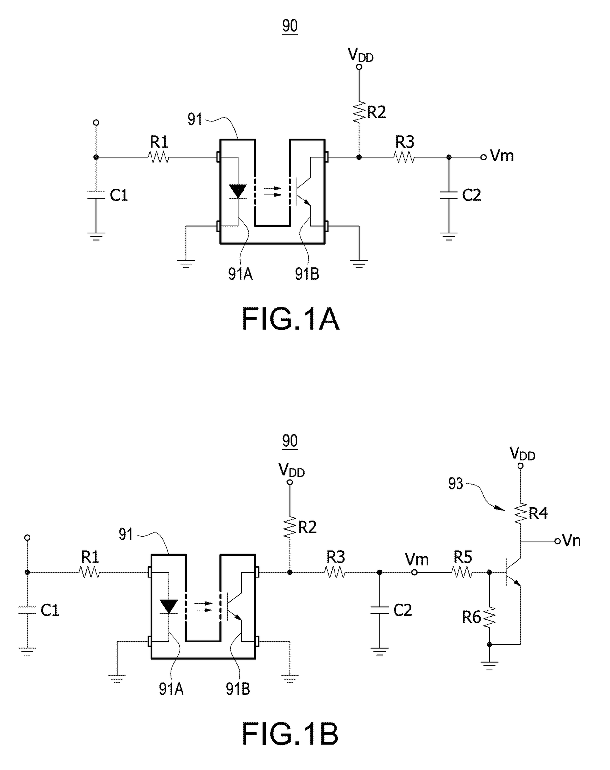
[0031]Please refer to FIG. 1A, which shows a circuit diagram of a home position detection circuit of a three-dimensional (3D) printer according to the present disclosure. The home position detection circuit 90 has a sensing switch. As shown in FIG. 1A, the sensing switch is, for example but not limited to, a contactless switch, such as a photo interrupter switch or a proximity switch. Also, the sensing switch may be a contact switch.

[0032]The above-mentioned proximity switch (also referred to as “non-contact travel switch”) may be classified into following types. The first one is an eddy current proximity switch (also referred to as “inductive proximity switch”). When a conductive object moves closer to the eddy current proximity switch, an internal eddy current is produced in the conductive object due to a generated electromagnetic field. The internal eddy current reacts to the eddy current proximity switch so as to change internal circuit parameters of the eddy current proximity s...

second embodiment

[0060]Please refer to FIG. 7C, which shows a flowchart of the method for compensating the home position of the 3D printer according to the present disclosure. Since the steps (S21) and (S22) shown in FIG. 7C are identical to the steps (S11) and (S12) shown in FIG. 7A, the detail descriptions of the steps (S21) and (S22) are omitted here for conciseness. Similarly, the “wrong” home position where the Z-axis movable mechanism Za finally arrives is corrected or compensated in step (S23) after the determination in the step (S22) is “YES”.

[0061]In the step (S23), the movable mechanism further moves in a compensation distance corresponding to a correction coefficient value of the step compensation amount in the home direction, and the correction coefficient value is a positive number less than 1. In other words, the compensation distance in the second embodiment is less than the compensation distance in the first embodiment. In this embodiment, the correction coefficient value is introduc...


PUM

PropertyMeasurementUnit
voltageaaaaaaaaaa
power voltage VDDaaaaaaaaaa
voltageaaaaaaaaaa

Abstract

A calibration method for compensating a home position of a 3D printer is disclosed. According to a movement position of a movable mechanism of the 3D printer, a control voltage is provided to a microcontroller. The calibration method includes steps as follows. The movable mechanism moves in a home direction. It is to determine whether the microcontroller receives a first logic level signal which is transited according to the corresponding control voltage. If yes, the movable mechanism moves in a direction opposite to the home direction. It is to determine whether the microcontroller receives a second logic level signal which is transited according to the corresponding control voltage. If yes, the movable mechanism moves a compensation distance corresponding to a step compensation amount in the home direction. Therefore, the calibration method is provided to reduce circuit costs, simplify designs of control circuits, and accurately calibrate the home position.

Description

BACKGROUND OF THE INVENTIONTechnical Field[0001]The technical field relates to a calibration method, and more particularly to a calibration method for compensating home position of a three-dimensional printer.Description of Related Art[0002]In operations of a three-dimensional printer (hereinafter referred to as “3D printer”), an auto-home operation for each axis of the 3D printer is first performed so that the each axis is ready at its home position (original position) before the 3D starts to operate. After the home-position operation, the home positon is used to be a relative reference position for the corresponding operation axis. For example, the coordinate of the home position is the reference coordinate for commands in a G-code file. In other words, each axis of the 3D printer moves to positions specified according to the G-code commands after the home position is determined. Therefore, the accuracy of the home position of any one axis would affect the fineness of the printed ...

Claims


Application Information

Patent Timeline
Patent Type & Authority Applications(United States)
IPC IPC(8): B29C64/393B33Y50/02H02P8/08G05D3/20
CPCB29C64/393B33Y50/02H02P8/08G05D3/20G05D3/127G01B7/003G01B11/028B33Y50/00B29C64/386B29C64/205B29C64/227
Inventor HO, KWANHUANG, CHIEN-YINGCHANG, CHIH-MINGLEE, CHIH-HAOTENG, HUNG-TANGYANG, CHUNG-CHIH
Owner XYZPRINTING
Why Eureka
Try Eureka